Mixing apparatus, dispersion manufacturing apparatus and dispersion manufacturing method

a technology of mixing apparatus and manufacturing apparatus, which is applied in the direction of azo dye coupling reaction, transportation and packaging, printing, etc., can solve the problems of not always easy to stably obtain pigment suspension, clogging of the nozzle of the ink jet head, and probably inferior pigment dispersion ink to dye ink, etc., to achieve efficient mixing and chemical reaction, small variation in fluid ejection, and small variation

Inactive Publication Date: 2008-12-18
CANON KK
View PDF3 Cites 12 Cited by
  • Summary
  • Abstract
  • Description
  • Claims
  • Application Information

AI Technical Summary

Benefits of technology

[0020]According to the mixing apparatus of the present invention, arranging a plurality of nozzles (nozzle openings) ejecting the same fluid to a supplying channel for supplying fluid at an equivalent position allows variation in ejection of fluid to be made small. This enables variation in mixing and chemical reaction between the fluid to be made sma

Problems solved by technology

However, the pigment dispersion ink is probably inferior to dye ink.
Coarse pigment particles cause clogging of the nozzle of an ink jet head.
Solution ejected from the nozzle may cause pigments formed by precipitation in the reactor chamber to stick to the

Method used


Image

  • Mixing apparatus, dispersion manufacturing apparatus and dispersion manufacturing method
  • Mixing apparatus, dispersion manufacturing apparatus and dispersion manufacturing method
  • Mixing apparatus, dispersion manufacturing apparatus and dispersion manufacturing method

Examples


embodiments

[0070]The present invention is described in detail below with reference to embodiments. The present invention, however, is not limited to the embodiments.

first embodiment

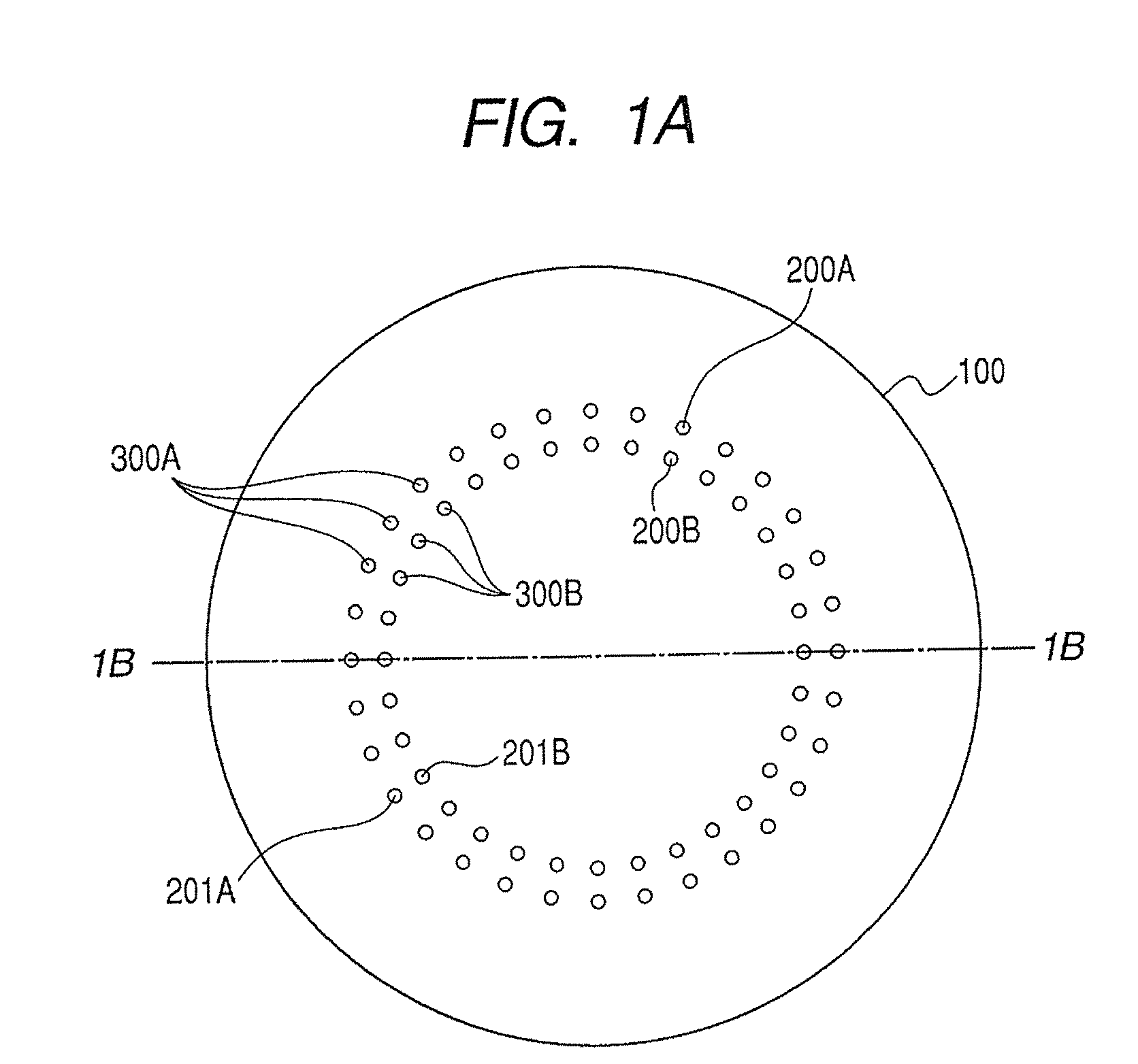
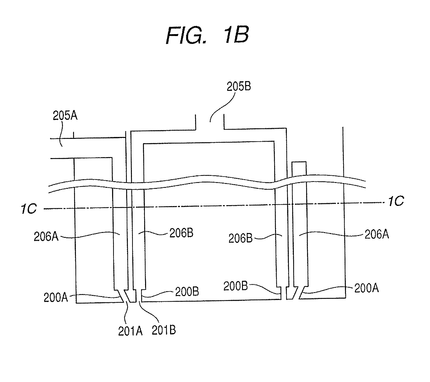
[0071]A mixing apparatus of the present embodiment is described with reference to FIGS. 1A, 1B and 1C.

[0072]A mixing apparatus 100 includes nozzles 200A and 200B, nozzle groups 300A and 300B, supplying channels 206A and 206B and fluid inlet 205A and 205B formed by a stainless steel member. Fluid ejected from the nozzle groups is introduced from their respective fluid inlets and supplied through the supplying channels. That is to say, fluid 1 is introduced from the fluid inlet 205B, passes through supplying channel 206B and ejected from the nozzle group 300B. Fluid 2 is introduced from the fluid inlet 205A, passes through supplying channel 206A and ejected from the nozzle group 300A. The fluids 1 and 2 ejected in a thin-rod shape from the nozzle groups 300B and 300A are brought into contact in areas on the extending lines of the nozzles to start mixing. Chemical reaction may or may not be involved between two different kinds of the fluids introduced in mixing.

[0073]As illustrated in ...

second embodiment

[0080]In the present embodiment, the mixing apparatus of the first embodiment is used to produce a dispersion of magenta pigment by reprecipitation reaction.

[0081]A hundred parts of dimethyl sulfoxide were added to 10 parts of quinacridon pigment of C.I. Pigment Red 122 as fluid 1 to perform suspension. Subsequently, 40 parts of sodium lauryl sulfate as a dispersant were added and 25% potassium hydroxide aqueous solution was added to such an extent that these dissolve to prepare the fluid 1. Ion-exchange water was used as the fluid 2. The fluid 1 was introduced from the fluid inlet 205B and passed through the supplying channel 206B and ejected from the nozzle group 300B. The fluid 2 was introduced from the fluid inlet 205A and passed through the supplying channel 206A and ejected from the nozzle group 300A. A syringe pump was used as a fluid supplying unit to supply the fluids 1 and 2 to the their respective nozzles.

[0082]The flow rate of the nozzle 200B ejecting the fluid 1 from th...


PUM

PropertyMeasurementUnit
Diameteraaaaaaaaaa
Diameteraaaaaaaaaa
Lengthaaaaaaaaaa

Abstract

A mixing apparatus including a plurality of nozzle groups each formed of nozzles for ejecting the same fluid arranged in group, the nozzles being provided with openings for ejecting fluid, to cause the plurality of nozzle groups to separately eject a plurality of fluids to mix the fluids in areas on the extending lines of the nozzles, wherein the openings of the nozzles forming the nozzle groups are arranged along annular loci and the plurality of nozzle groups are arranged coaxially to each other, a plurality of supplying channels for supplying the plurality of fluids to the nozzle groups corresponding to the plurality of nozzle groups are annular in cross section in the direction perpendicular to the direction in which fluid supplied to the supplying channels flows and arranged coaxially to each other.

Description

BACKGROUND OF THE INVENTION[0001]1. Field of the Invention[0002]The present invention relates to a mixing apparatus for manufacturing materials and products by mixture and reaction of fluids, a dispersion manufacturing apparatus and a dispersion manufacturing method in the chemical and pharmaceutical industries.[0003]2. Description of the Related Art[0004]As an aqueous dispersion material containing functional material, there have been hitherto known functional materials composed of agricultural chemicals such as herbicide and insecticide, medicine such as anticancer drug, antiallergic agent and antiphlogistine, and colorant such as ink with colorant and toner. A digital printing technique has made significant progress in recent years. A typical digital printing technique is electrophotography and ink jet technique and has enhanced its presence as an image forming technique in office and home in late years.[0005]In the digital printing technique, the ink jet technique as a direct re...

Claims


Application Information

Patent Timeline
IPC IPC(8): B41J2/145
CPCB01F3/12B01F5/0256B01F13/1013B01F13/1022B01F2003/125B01F2215/005C09B41/008B01F23/50B01F23/56B01F25/23B01F33/81B01F33/813B01F2101/30
Inventor TESHIMA, TAKAYUKINAKAHAMA, KAZUMICHIHANYU, YUKIO
Owner CANON KK
Why Eureka
Try Eureka