Systems and methods for laser radar imaging for the blind and visually impaired

a laser radar and blind and visually impaired technology, applied in the field of vision enhancement, can solve the problems of age-related visual impairment and blindness, crude deficiency in the current art, and continue to increase, and achieve the effect of high accuracy

Inactive Publication Date: 2008-12-18
FALLON JAMES JOHN
View PDF5 Cites 94 Cited by
  • Summary
  • Abstract
  • Description
  • Claims
  • Application Information

AI Technical Summary

Benefits of technology

[0042]This invention is directed to portable three dimensional imaging ladar systems utilized in conjunction with a near-field user interface to provide highly accurate three dimensional spatial object information for vision augmentation for the blind or visually impaired.

Problems solved by technology

With ever increasing life expectancies and over half of the 10 million visually impaired in the United States over age 60, it is anticipated that age related visual impairment and blindness will unfortunately continue to increase.
Perhaps the biggest deficiency in the current art is in the area of mobility assistance.
However, some visually impaired persons do not carry these kinds of canes, opting instead for the shorter, lighter identification (ID) cane.
However, they can only do this in a crude way by using a simple tone pulse, as the ultrasonic emission, in order to receive a detectable echo from the nearest object.
However, one significant limitation within the current art is that ultrasonic vision augmentation devices possess extremely poor spatial resolution and working distances.
Resolutions are quite poor, typically six degrees at best.
Another limitation within the current art is the need to manually switch between short and long distance modes of operation to garner reasonable user information.
Yet another limitation within the current art is the need to manually scan the ultrasonic device, typically in the horizontal direction, to discern object location within the field of view.
However a two dimensional detailed spatial distance map is not possible with the current technology.
Yet another limitation within the current art is the limited overall total field of view of the ultrasonic device which mandates manual scanning.
Yet another limitation within the current art is the need for continued use of a cane for orientation and mobility in conjunction with the ultrasonic device.
One limitation within the current art is that guide dogs may become distracted while performing their duties by loud noise or other types of events.
Another limitation within the current art is that guide dogs need extensive training, maintenance, and re-certification.
Another limitation of guide dogs is that although the dogs can be trained to navigate various obstacles, they are partially (red-green) color blind and are not capable of interpreting street signs.
Scanners are typically based upon piezoelectric or galvanometer technology, which places restrictions on the speed and inherent accuracy of image acquisition.
Limitations within the current art include the excessive size and weight of modern ladar systems, along with the volume, power, and costs of the system.

Method used


Image

  • Systems and methods for laser radar imaging for the blind and visually impaired
  • Systems and methods for laser radar imaging for the blind and visually impaired
  • Systems and methods for laser radar imaging for the blind and visually impaired

Examples


Embodiment Construction

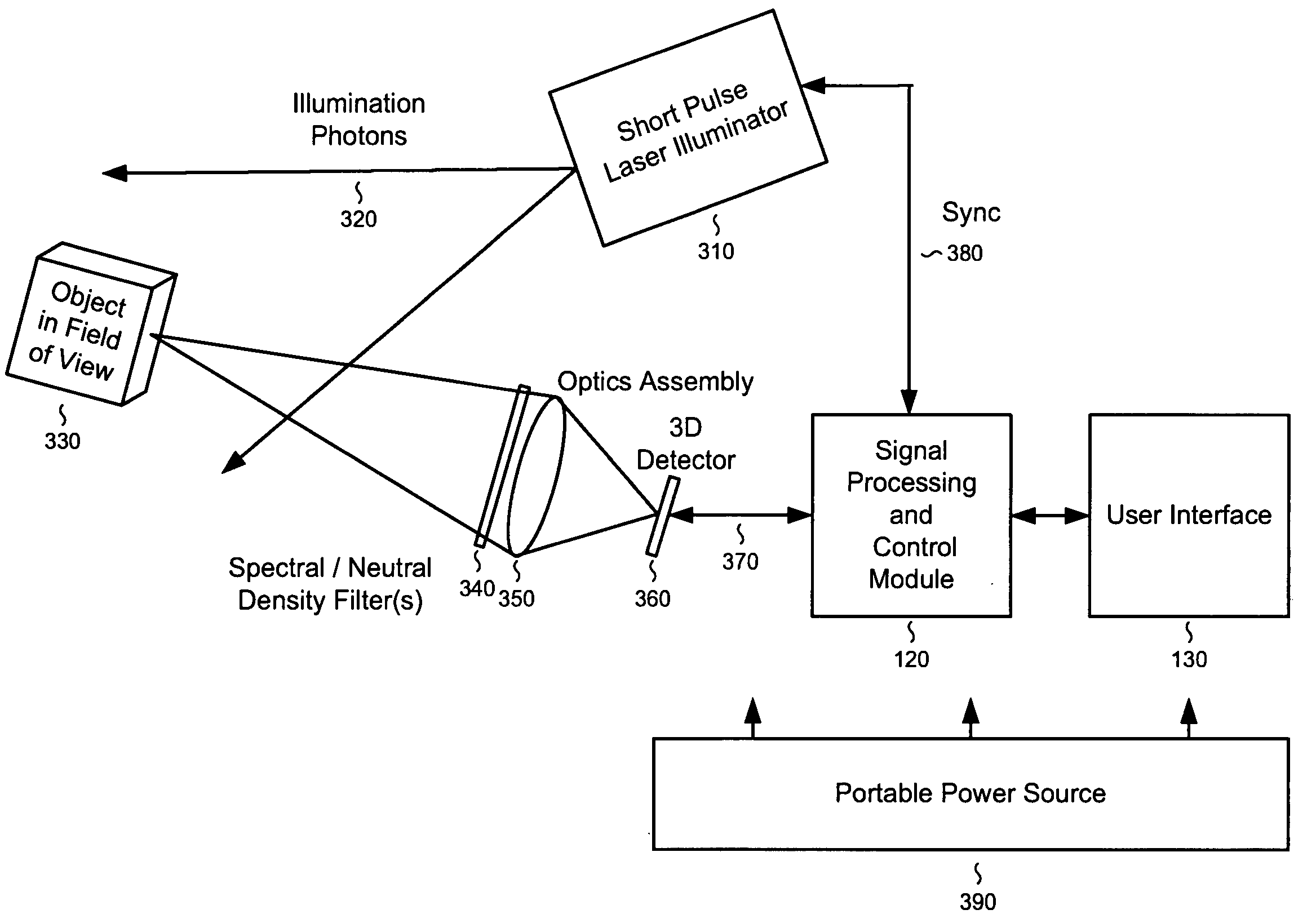
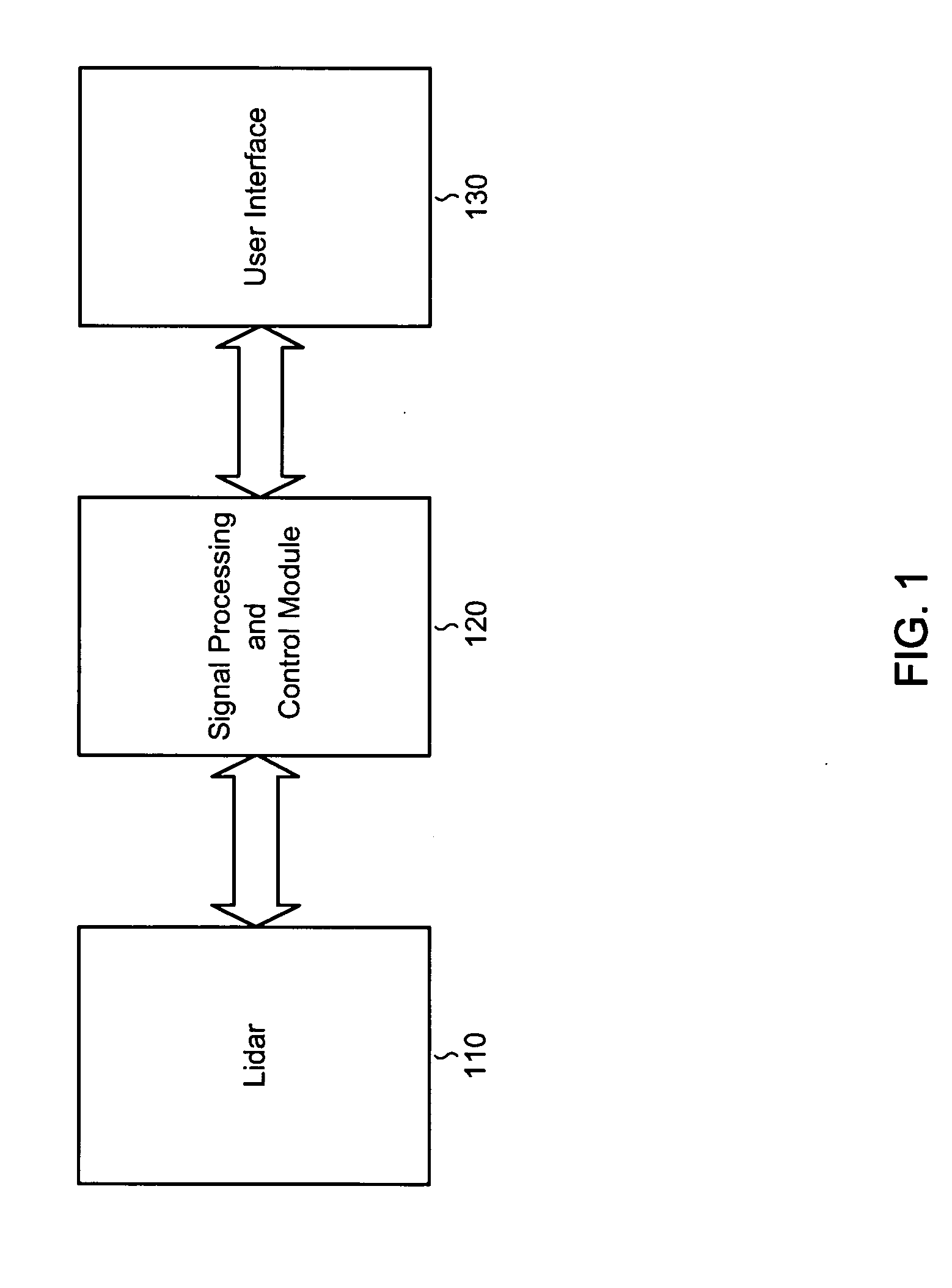
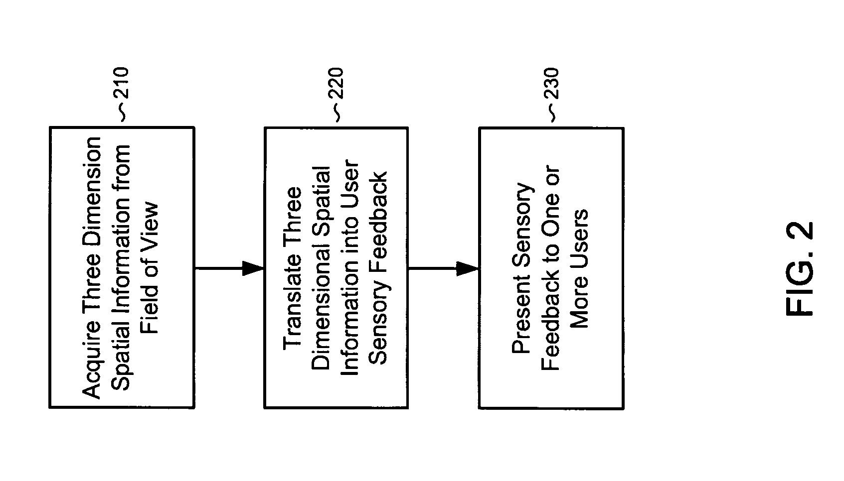
[0062]The present invention is directed to systems and methods for providing vision augmentation and, more particularly, to systems and methods for providing a three dimensional vision replacement and augmentation for the blind and visually impaired.

[0063]In the following description, it is to be understood that system elements having equivalent or similar functionality are designated with the same reference numerals in the figures. It is to be further understood that the present invention may be implemented utilizing a wide variety of components including, but not limited to light emitting diodes and solid state lasers, solid state imaging array detectors that operate in the ultraviolet, visible, infrared wavelengths, static and scanning optical systems, image processing and recognition hardware and software, general purpose and digital signal processors, hardware, software, and firmware for system functionality including user interface, data processing, and databases, portable pow...


PUM


Abstract

A 3D imaging ladar system comprises a solid state laser and geiger-mode avalanche photodiodes utilizing a scanning imaging system in conjunction with a user interface to provide 3D spatial object information for vision augmentation for the blind. Depth and located object information is presented acoustically by: 1) generating an audio acoustic field to present depth as amplitude and the audio image as a 2D location. 2) holographic acoustical imaging for a 3D sweep of the acoustic field. 3) a 2D acoustic sweep combined with acoustic frequency information to create a 3D presentation.
A system to fuse data derived from a three dimensional imaging ladar system with information from a visible, ultraviolet, or infrared camera systems and acoustically present the information in a four or five dimensional acoustical format utilizing three dimensional acoustic position information, along with frequency, and modulation to represent color, texture, or object recognition information is also provided.

Description

RELATED US APPLICATION DATA[0001]This application claims the benefit of U.S. Provisional Patent Application No. 60 / 934,990 filed on Jun. 14, 2007, which is incorporated by reference herein in its entirety.BACKGROUND OF THE INVENTION[0002]The present invention relates generally to vision augmentation and, more particularly, to systems and methods for providing a three dimensional vision replacement and augmentation for the blind and visually impaired.[0003]The World Health Organization estimates that in 2002 approximately 161 million (2.6% of the world's population) are visually impaired, of which 124 million (2.0%) have significantly impaired vision and 40 million are blind. According to the American Foundation for the Blind there are approximately 10 million blind and visually impaired people in the United States of which approximately 1.3 million Americans are legally blind. The legal definition of blindness refers to central visual acuity of 20 / 200 or less in the better eye with ...

Claims


Application Information

Patent Timeline
Patent Type & Authority Applications(United States)
IPC IPC(8): G01C3/08H01L25/00
CPCA61H3/061G01S17/89
Inventor FALLON, JAMES JOHN
Owner FALLON JAMES JOHN
Why Eureka
Try Eureka