Method for detecting objects with visible light

a technology of visible light and detection method, which is applied in the direction of distance measurement, instruments, and using reradiation, can solve the problems of poor color rendering of white pcleds, limited use of high-accuracy optical detection, and ranging of targets or obstacles located at close to medium range, and achieves the risetime of white pcleds very fast, long decay life, and increase of the overall duration of light pulses

a technology of visible light and detection method, which is applied in the direction of distance measurement, instruments, and using reradiation, can solve the problems of poor color rendering of white pcleds, limited use of high-accuracy optical detection, and ranging of targets or obstacles located at close to medium range, and achieves the risetime of white pcleds very fast, long decay life, and increase of the overall duration of light pulses

US20080309914A1Active Publication Date: 2008-12-18LEDDARTECH INC

Image

  • Method for detecting objects with visible light
  • Method for detecting objects with visible light
  • Method for detecting objects with visible light

Examples


Embodiment Construction

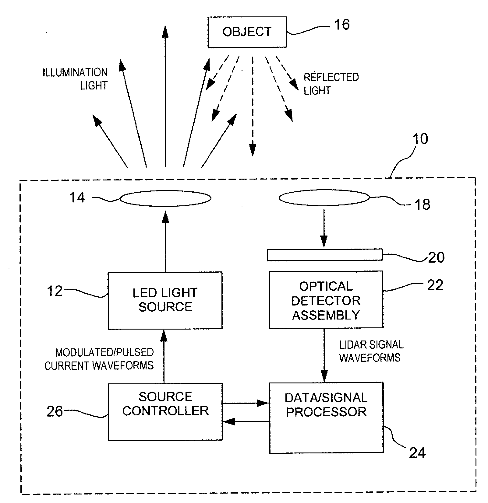
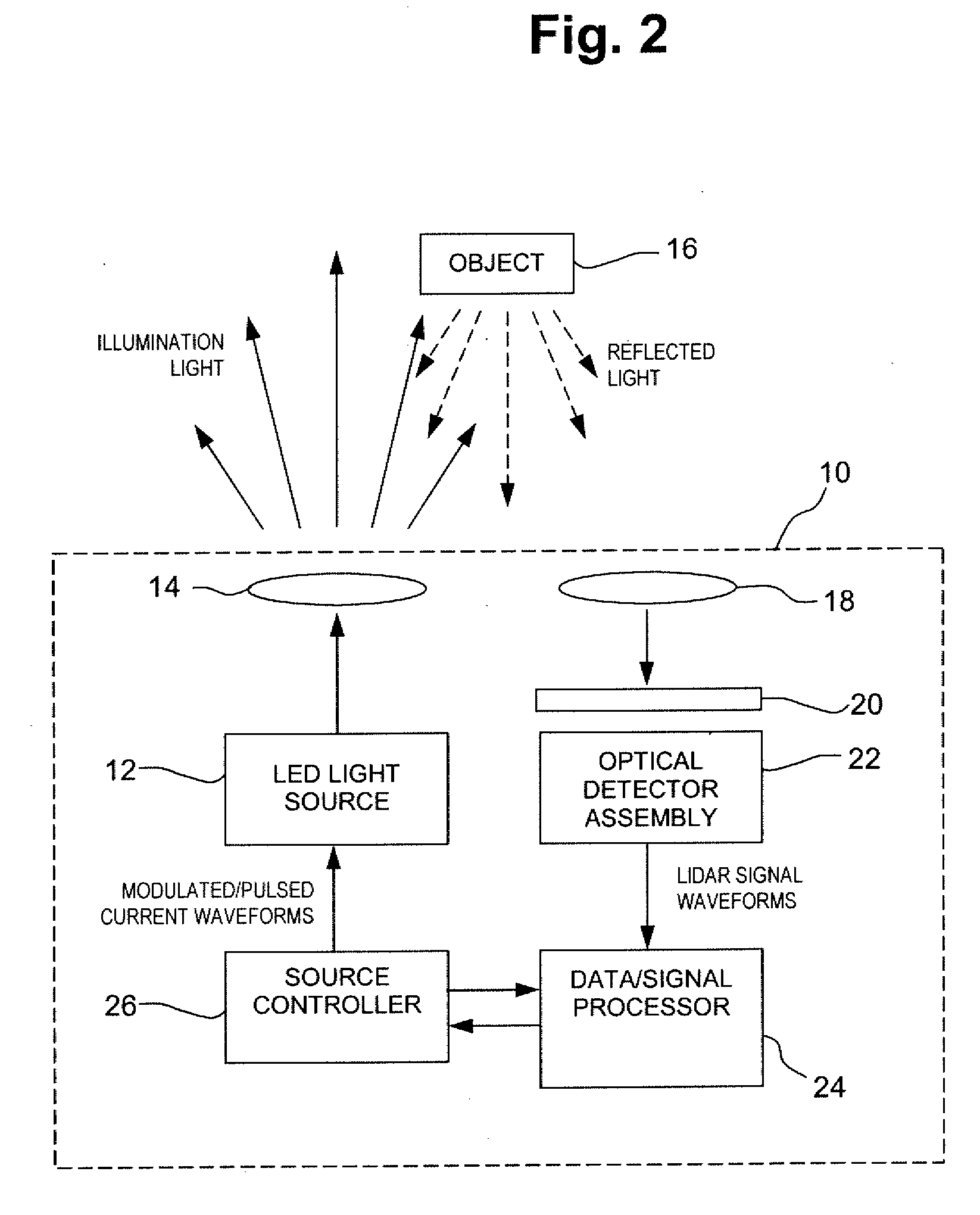
[0027]Reference will now be made in detail to the preferred embodiments of the invention. This invention may, however, be embodied in many different forms and should not be construed as limited to the embodiments set forth in the following description. The main features of an apparatus built in accordance with an embodiment of the present application can be better understood by referring to FIG. 2 which shows a dual-function lighting system 10 that provides standard illumination along with lidar capabilities for detecting remote obstacles or targets.

[0028]The lighting system 10 includes a light source 12 that emits visible light, in order to illuminate an environment according to its primary function. The light passes through the emission optics 14 before escaping from the lighting system 10. The emission optics 14 ensures that the light gets an angular radiation pattern suited for either general or application-dependent illumination purposes. The light source 12 then enables the sy...


PUM

PropertyMeasurementUnit
wavelength rangeaaaaaaaaaa
wavelengthaaaaaaaaaa
color temperatureaaaaaaaaaa

Abstract

A method for detecting an object using visible light comprises providing a visible-light source having a function of illuminating an environment. The visible-light source is driven to emit visible light in a predetermined mode, with visible light in the predetermined mode being emitted such that the light source maintains said function of illuminating an environment. A reflection / backscatter of the emitted visible light is received from an object. The reflection / backscatter is filtered over a selected wavelength range as a function of a desired range of detection from the light source to obtain a light input. The presence or position of the object is identified with the desired range of detection as a function of the light input and of the predetermined mode.

Description

CROSS-REFERENCE TO RELATED APPLICATION[0001]This patent application claims priority on U.S. Provisional Patent Application No. 60 / 944,649, filed on Jun. 18, 2007.FIELD OF THE APPLICATION[0002]The present application relates to a method and an apparatus implementing such a method that enable the use of a single broadband solid-state light source in a lighting system that performs its intended lighting function in addition to a lidar function for optical detection and ranging of remote obstacles or aimed targets.BACKGROUND OF THE APPLICATION[0003]Light-emitting diodes (LEDs) are at the heart of solid-state lighting devices, which are gaining acceptance for use in a wide range of applications from traffic lights to large flat panel displays. Until now, the most common LED-based source of white light has been the so-called phosphor-converted LED (pcLED). A pcLED typically consists of a LED made from a single chip of a III-V semiconductor material such as indium gallium nitride (InGaN), ...

Claims


Application Information

Patent Timeline
18 Dec 2008
Publication
US20080309914A1
IPC
G01C3/08; G01N21/47; G01S17/10
CPC
G01S17/10
Inventors
CANTIN, DANIEL; GALLANT, PASCAL