Hologram Screen

Inactive Publication Date: 2008-12-18
SUMITOMO ELECTRIC IND LTD
View PDF5 Cites 4 Cited by
  • Summary
  • Abstract
  • Description
  • Claims
  • Application Information

AI Technical Summary

Benefits of technology

[0024]A holographic screen according to the present invention includes a DLC layer and therefore has much higher durability as compared to conventional

Problems solved by technology

Therefore, in the half-mirror screen, there is a problem in that the utilization efficiency of light projected from a pr

Method used


Image

  • Hologram Screen
  • Hologram Screen
  • Hologram Screen

Examples


Example

EXPLANATION OF REFERENCED NUMERALS

[0031]2 glass plate[0032]5 car[0033]21 silica glass substrate[0034]22 DLC layer[0035]22a low-refractive-index regions[0036]22b high-refractive-index regions[0037]23a and 23b silica glass substrates[0038]24a and 24b gold masks[0039]25a and 25b UV beams[0040]31 transmissive holographic screen[0041]32 reflective holographic screen[0042]34 gold mask[0043]35 He ion beam[0044]41 slide projector[0045]42 liquid crystal (LC) projector[0046]51 car dashboard[0047]91 observer

BEST MODE FOR CARRYING OUT THE INVENTION

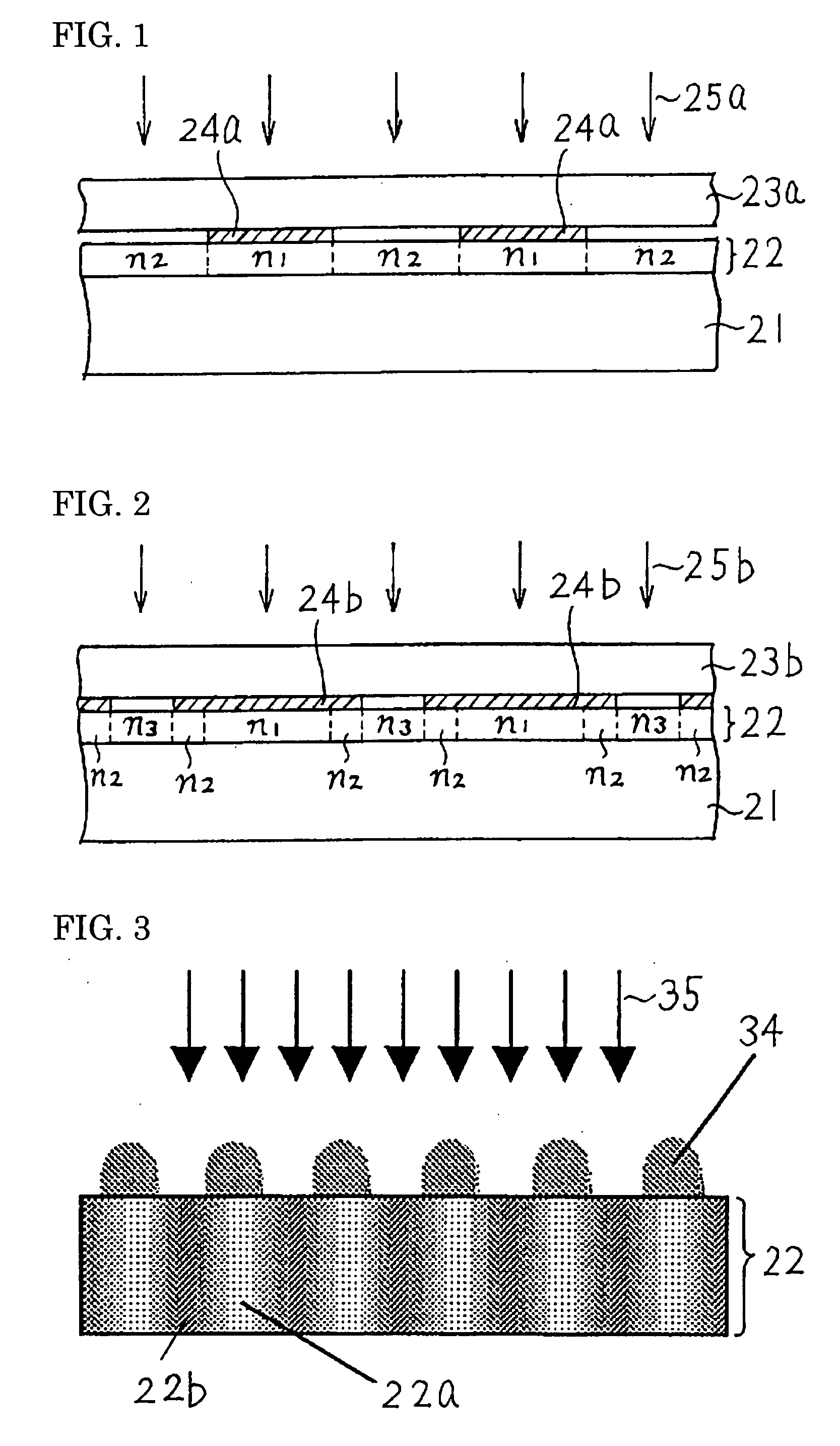
[0048]Before the present invention has been made, the inventors have confirmed that a light-transmissive DLC layer can be increased in refractive index by irradiating the DLC layer with an energy beam. The DLC layer can be formed on a substrate such as a silicon substrate, a glass substrate, or another material substrate by plasma chemical vapor deposition (CVD). The light-transmissive DLC layer formed by such plasma CVD usually has a refractive index...


PUM


Abstract

The present invention provides a holographic screen having high durability and high diffraction efficiency due to a modulated refractive index structure having a large refractive index change Δn.
The holographic screen includes a diamond-like carbon (DLC) layer (22). The DLC layer has a modulated refractive index structure including a plurality of regions with a relatively high refractive index (n1) and a plurality of regions with a relatively low refractive index (n2) such that light projected from a projector onto the screen is deflected in the direction toward a observer and light coming from an object behind the screen is allowed to pass through the screen to travel toward the observer.

Description

TECHNICAL FIELD[0001]The present invention relates to screens for displaying characters or images projected from projectors and particularly relates to a holographic screen that allows an observer to see both an image projected from a projector onto the screen and an object behind the holographic screen at the same time.BACKGROUND ART[0002]The following screens can be used for various applications: screens having a function of allowing observers to see both images projected from projectors onto the screens and objects behind the holographic screens at the same time. Hence, attempts are being made to develop the screens. This type of screen allows an observer to see two images at the same time and therefore is called a combiner.[0003]The simplest example of a screen functioning as a combiner is a half-mirror screen. The half-mirror screen reflects a component of light projected from a projector toward an observer and allows a component of light coming from an object behind the half-m...

Claims


Application Information

Patent Timeline
IPC IPC(8): G03B21/60G02B5/32G03H1/04G03H1/18
CPCG02B5/32G02B27/0103G02B2027/0118G03H1/02G03H2001/0268G03H2240/54G03B21/62
Inventor USHIRO, TOSHIHIKOODA, KAZUHIKOMATSUURA, TAKASHI
Owner SUMITOMO ELECTRIC IND LTD
Why Eureka
Try Eureka