Ramping in Multimode Transmitters Using Primed Filters

a multi-mode transmitter and prime filter technology, applied in the field of modulator apparatus, can solve the problems of affecting the processing speed of baseband processors, the inability to easily control the modulator response profile during ramping periods, and the contention for processing tim

Inactive Publication Date: 2008-12-18
NORTH STAR INNOVATIONS
View PDF9 Cites 5 Cited by
  • Summary
  • Abstract
  • Description
  • Claims
  • Application Information

AI Technical Summary

Problems solved by technology

However, the profile of modulator response during ramping periods cannot be controlled easily, beyond the fixed ramping profile used.
Such inflexibility is disadvantageous, because the guard band period can, in some circumstances (such as an Access Burst followed by a Normal Burst having up to a 63 symbol timing advance in a multi-slot transmission), vary leading to shortened guard band periods during which the response of the modulator has to ramp up or down at a fixed rate, resulting in contention for processing time.
Additionally, some power amplifier circuits used to amplify modulated signals do not ramp up and “settle” or ramp down and settle symmetrically in time.
2002 / 0176514 A1, additional information, which is appended and pre-pended to information symbols, which include trailing bits, to achieve the desired ramping profile, needs to be transferred from the baseband processor to the modulator, resulting in a software burden on the baseband processor.
Furthermore, a number of known transmitters are not capable of strict compliance with a standardised slot size of 156.25 symbols / slot due to an inability of some modulators to re-start in sufficient time in the guard band period at a quarter symbol boundary of a given slot.
The need to insert an additional symbol every fourth slot creates a processing burden on the baseband processor to maintain the non-uniform slot lengths over a number of slots transmitted.
However, when a need arises to switch between modulators, for example between a GMSK modulator and an 8 PSK modulator, the above-described solution, albeit problematic, is inapplicable, since a phase and amplitude discontinuities would occur between an undefined end point of phase and amplitude associated with the GMSK modulator and a starting phase and amplitude associated with the 8 PSK modulator.

Method used


Image

  • Ramping in Multimode Transmitters Using Primed Filters
  • Ramping in Multimode Transmitters Using Primed Filters
  • Ramping in Multimode Transmitters Using Primed Filters

Examples


Embodiment Construction

[0019]Throughout the following description identical reference numerals will be used to identify like parts.

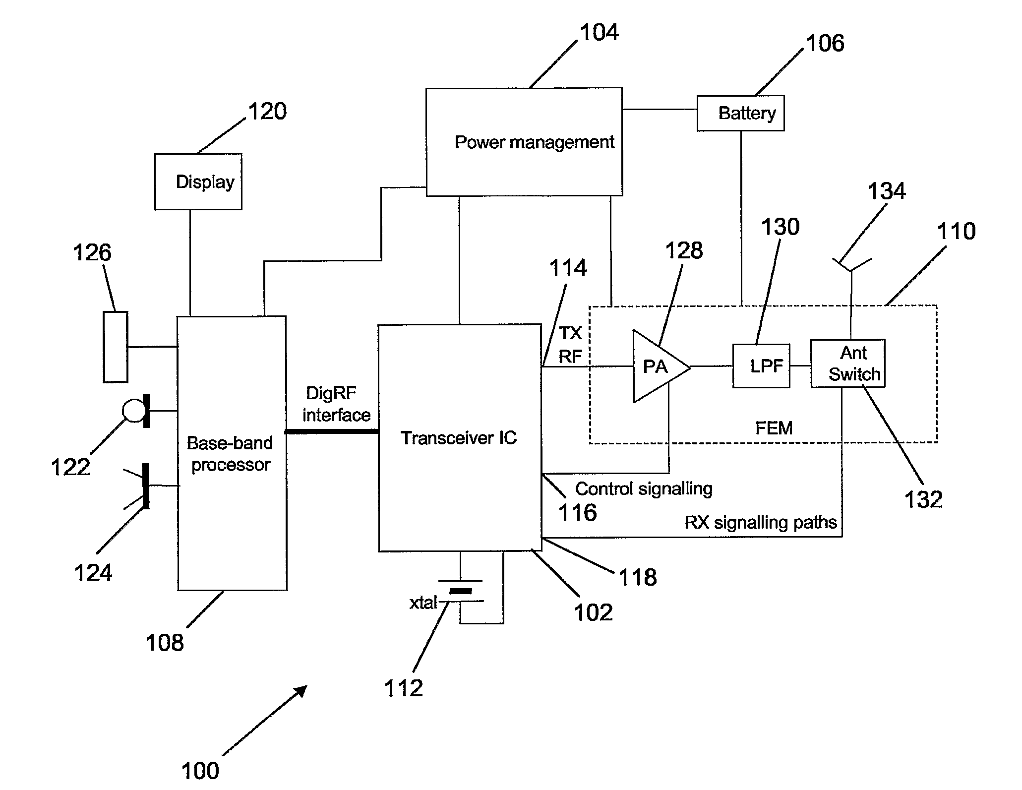
[0020]Referring to FIG. 1, a communications apparatus 100, for example a wireless communications device, such as a cellular telephone handset, comprises a transceiver Integrated Circuit (IC) 102, the transceiver IC 102 coupled to a power management unit 104. The power management unit 104 is coupled to a power source, for example a battery 106, and a baseband processor unit 108. The power management unit 104 and the battery 106 are also coupled to a front-end module 110.

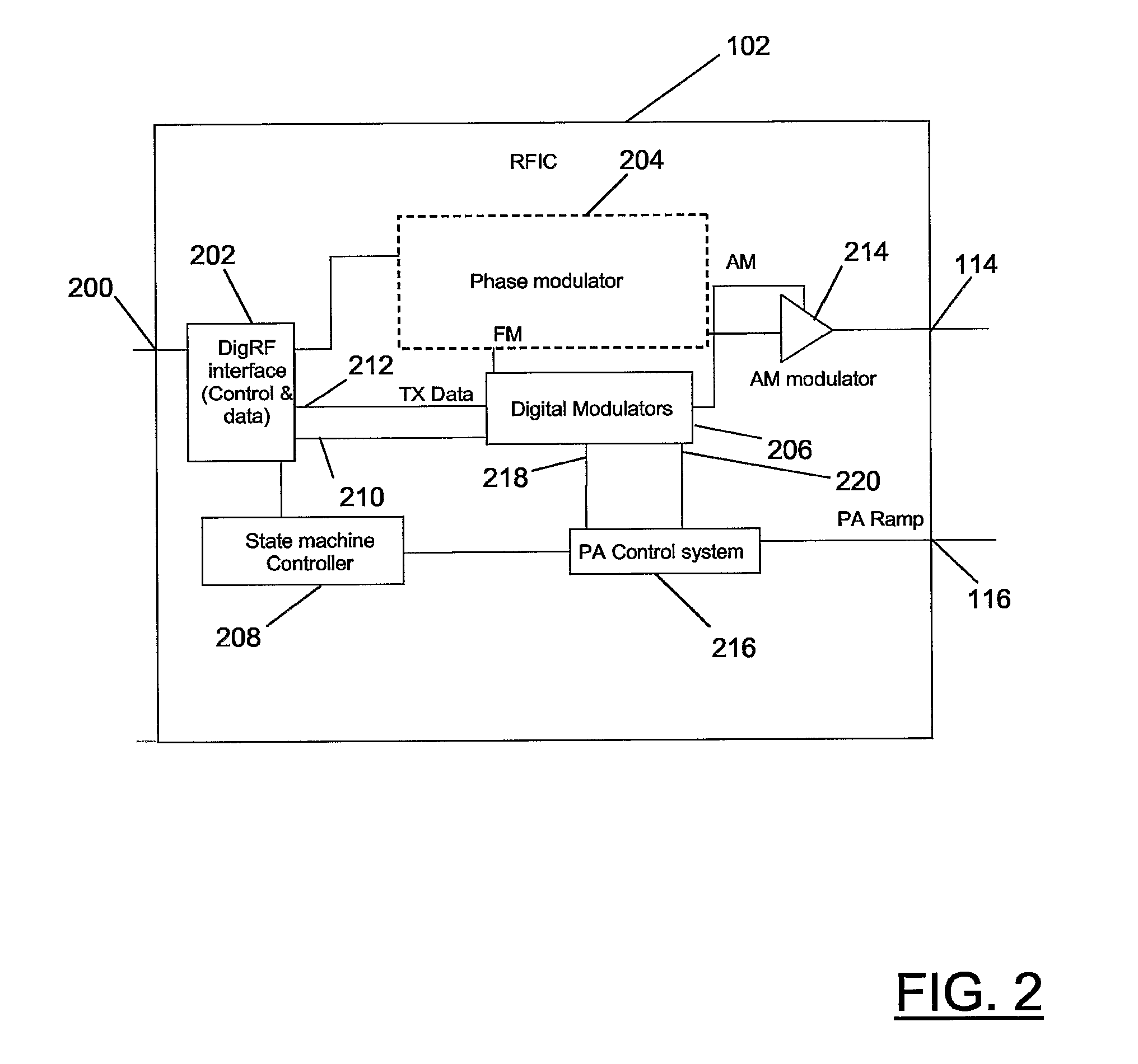
[0021]As well as being coupled to the baseband processor unit 108 and the front-end module 110, the transceiver IC 102 is also coupled to a crystal 112 that serves as a source of a reference clock signal. Additionally, the transceiver IC 102 is coupled to the front-end module 110 via a transmission Radio Frequency (RF) output 114, a control signalling output 116 and a receiver signalling input 118.

[0022]For the ...


PUM


Abstract

A modulation system can switch between two modulation modes. In order to comply with limits on peak power in spectral bands outside the RF operating one the transmitter is required to ramp down to a condition of minimal power. To avoid fixed ramping and trailing bits, the transmitting signal is subjected to FIR filtering. The two FIR filters are primed with a sequence using a parallel input mode before serially entering the information data.

Description

FIELD OF THE INVENTION[0001]This invention relates to a modulator apparatus of the type, for example, comprising a digital filter. This invention also relates to a modulation system of the type, for example, comprising a modulator apparatus coupled to a controller. This invention further relates to a method of controlling an output of a modulator apparatus.BACKGROUND OF THE INVENTION[0002]In the field of wireless communications, in particular cellular communications, existing cellular telecommunications systems now support so-called 2.5 G and 3 G features. In this respect, support is now available for high-speed data communications in Global System for Mobile communications (GSM) networks, known as Enhanced Data rates for GSM Evolution (EDGE) or an Enhanced General Packet Radio Service (EGPRS).[0003]To support EGPRS, wireless communications handsets, referred to as Mobile Stations (MSs) in some telecommunications standards, are typically equipped with a number of transmit modulator ...

Claims


Application Information

Patent Timeline
Patent Type & Authority Applications(United States)
IPC IPC(8): H04L27/22
CPCH03G3/3047H04L27/0008H04L27/2017
Inventor O'KEEFE, CONNOR J.O'SULLIVAN, ROBERTPRATT, PATRICK
Owner NORTH STAR INNOVATIONS
Why Eureka
Try Eureka