Optical Transmission Equipment and Method for Controlling Thereof

a technology of optical transmission equipment and control method, which is applied in the field of optical transmission equipment, can solve the problems of not considering the possibility of reducing the rate of further occurrence of errors in the change of transmission line dispersion

Inactive Publication Date: 2008-12-18
HITACHI LTD
View PDF6 Cites 4 Cited by
  • Summary
  • Abstract
  • Description
  • Claims
  • Application Information

AI Technical Summary

Benefits of technology

[0007]The above described problem can be solved by optical transmission equipment including: a wavelength demultiplexer for demultiplexing a transmitted wavelength-multiplexed signal to a first optical signal of a first wavelength and to a second optical signal of a second wavelength; a first variable dispersion compensation unit for compensating the dispersion of the first optical signal; a second variable dispersion compensation unit for compensating the dispersion of the second optical signal; a first error detector for detecting a signal error in the first optical signal which has been subjected to dispersion compensation; a second detector for detecting a signal error in the second optical signal which has been subjected to dispersion compensation; and a dispersion compensation control unit connected to the first variable dispersion compensation unit, the second variable dispersion compensation unit, the first error detector, and the second error detector. The dispersion compensation control unit controls dispersion compensation amounts of the first and second variable dispersion compensation units, based on the detectio

Problems solved by technology

As a result, there is no consideration of reducing the rate of further

Method used


Image

  • Optical Transmission Equipment and Method for Controlling Thereof
  • Optical Transmission Equipment and Method for Controlling Thereof
  • Optical Transmission Equipment and Method for Controlling Thereof

Examples


Embodiment Construction

[0024]Hereinafter, preferred embodiments of the present invention will be described with reference to the accompanying drawings. Like or corresponding parts are denoted by the same reference numerals and the description is not repeated.

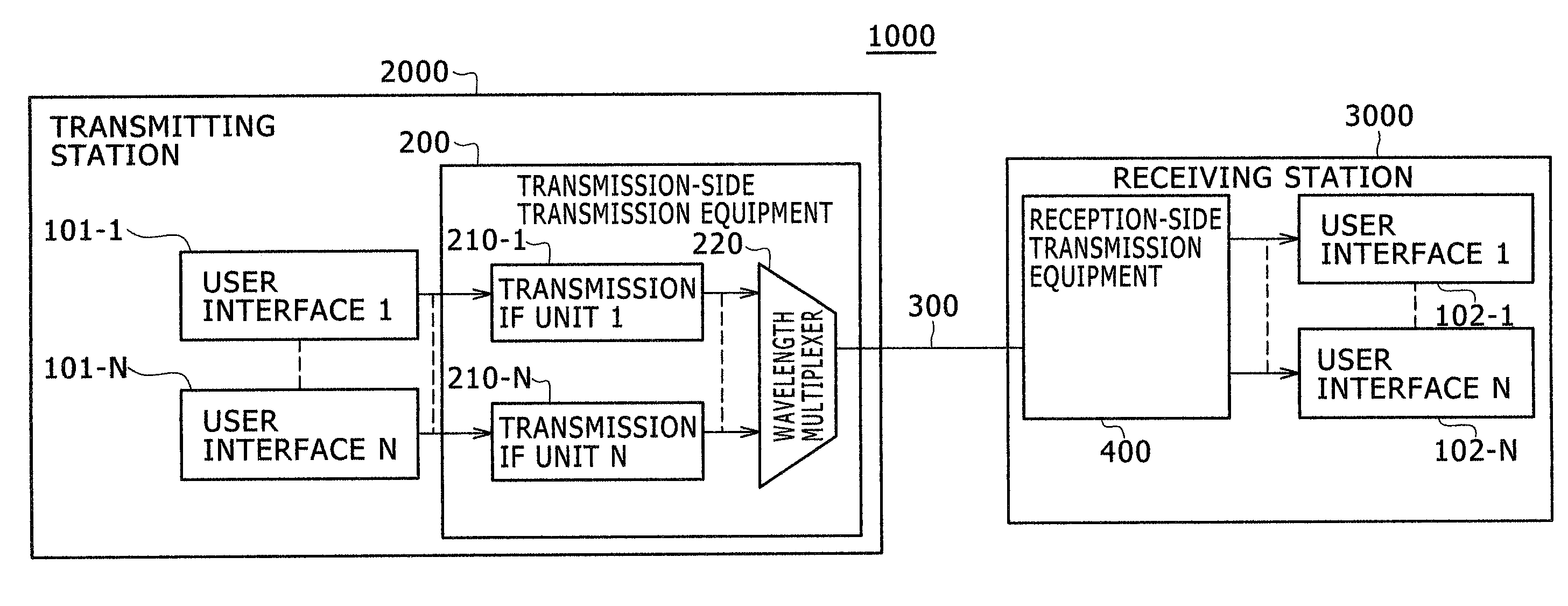
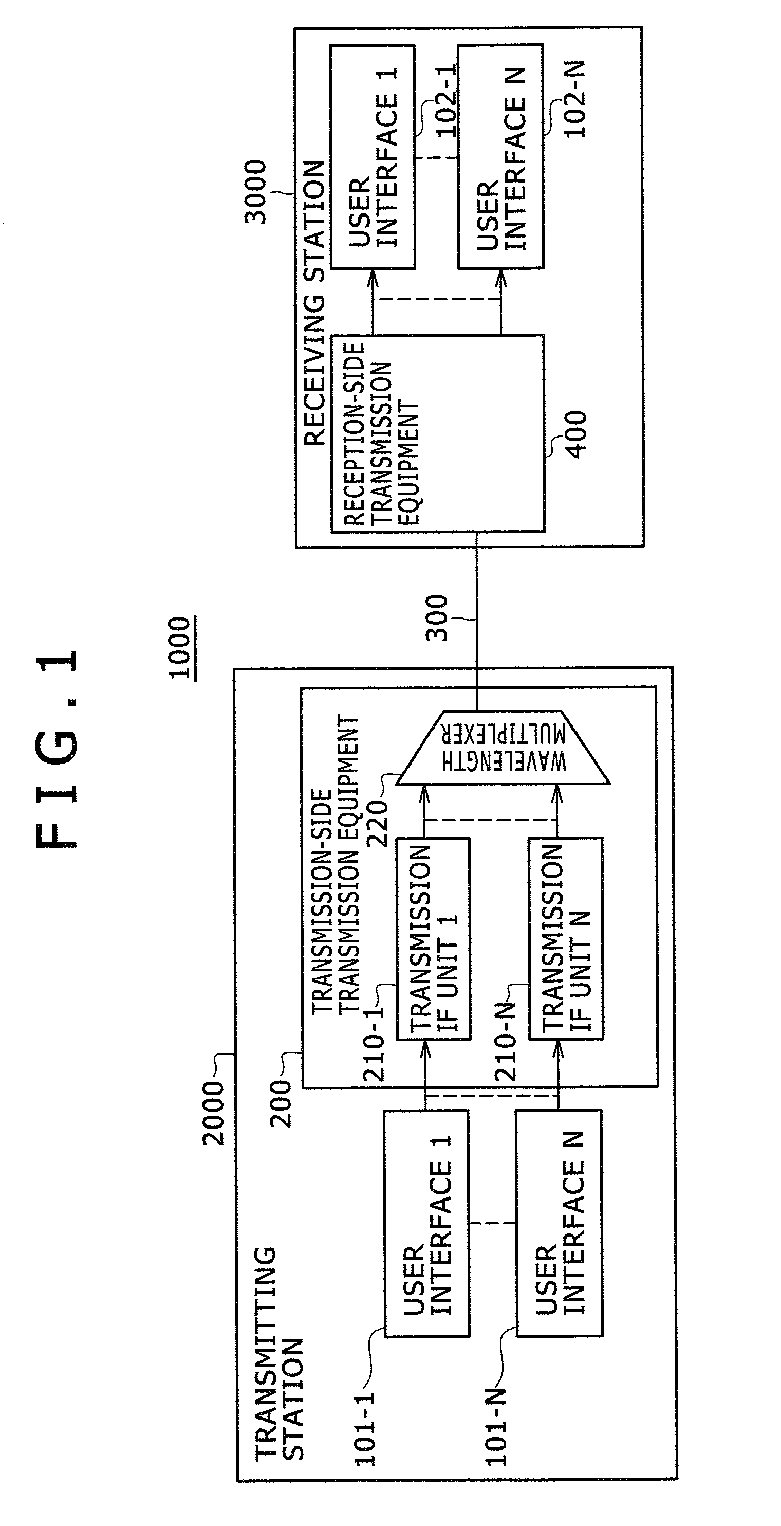
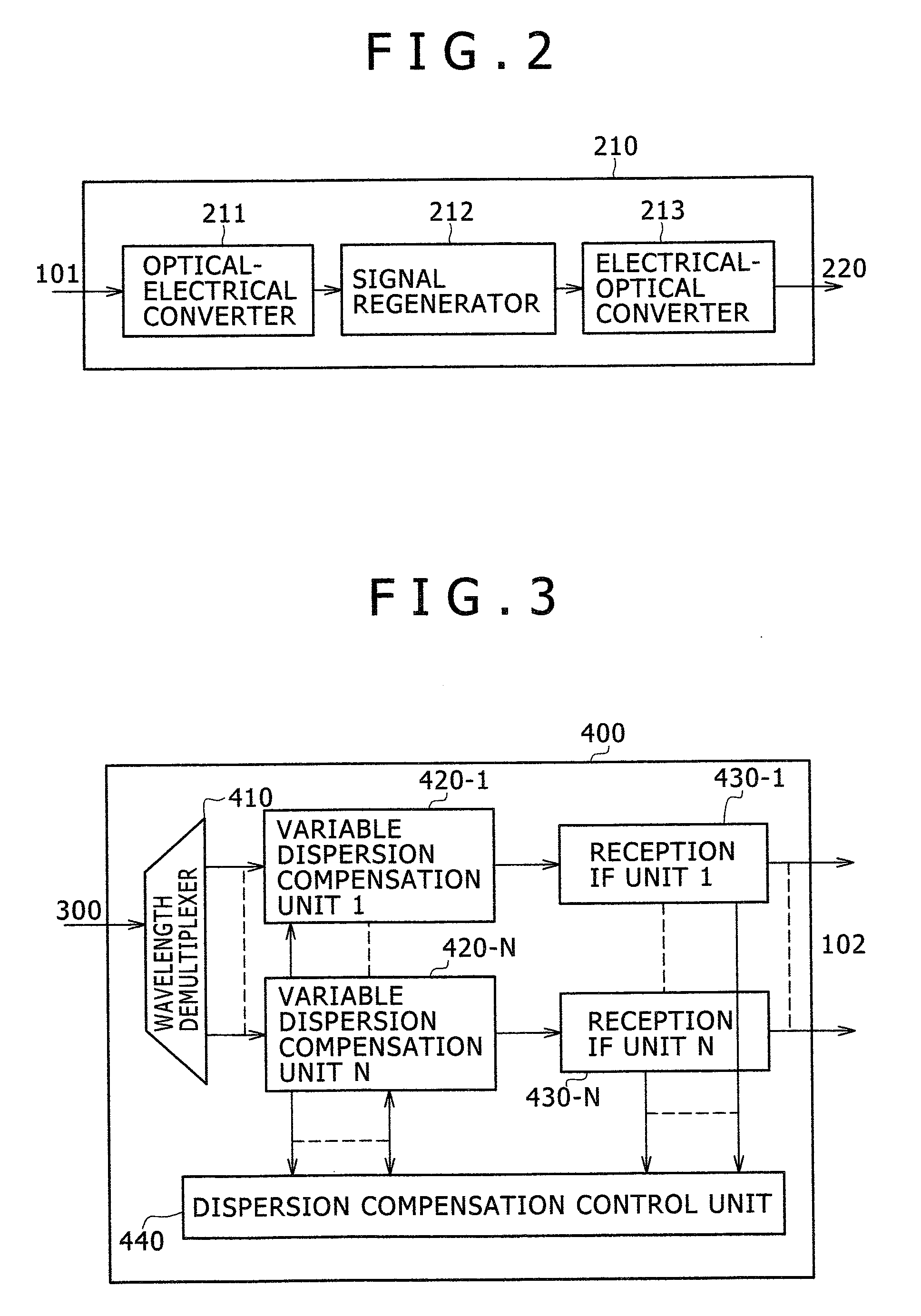
[0025]Here, FIG. 1 is a block diagram of an optical transmission system. FIG. 2 is a block diagram of a transmission IF unit. FIG. 3 is a block diagram of a reception-side transmitter. FIG. 4 is a block diagram of a variable dispersion compensation unit. FIG. 5 is a block diagram of a reception IF unit. FIG. 6 is a block diagram of a dispersion compensation control unit. FIG. 7 is flowchart illustrating error detection control of the reception-side transmitter. FIG. 8 is a view showing changes in the transmission line dispersion value. FIG. 9 is a view showing residual dispersion values and dispersion tolerances. FIG. 10 is a view showing residual dispersion values and dispersion tolerances upon occurrence of an error. FIG. 11 is a view showing residu...


PUM


Abstract

The optical transmission equipment includes: a demultiplexer for demultiplexing a transmitted wavelength-multiplexed optical signal to first and second optical signals; a first variable dispersion compensation unit; a second variable dispersion compensation unit; a first error detector; a second error detector; and a dispersion compensation control unit for controlling dispersion compensation amounts of the first and second variable dispersion compensation units based on the detection result of the first or second error detector. Upon detection of a signal error in the first optical signal, the first variable dispersion compensation unit is controlled to change from a first compensation amount to a third compensation amount, and the second variable dispersion compensation unit is controlled to change from a second compensation amount to a fourth compensation amount.

Description

CLAIM OF PRIORITY[0001]The present application claims priority from Japanese patent application serial no. 2007-156698, filed on Jun. 13, 2007, the content of which is hereby incorporated by reference into this application.BACKGROUND OF THE INVENTION[0002]The present invention relates to optical transmission equipment and a method for controlling the optical transmission equipment. More particularly, the present invention relates to optical transmission equipment for an optical transmission system for multiplexing and transmitting plural signal lights, and to a method for controlling the optical transmission equipment.[0003]As a dispersion compensation method, there is a control method for reducing signal errors. This method changes the dispersion value by a variable dispersion compensator when a signal error occurs due to dispersion changes resulting from the change in the transmission line characteristics or other factors. In this way, the method controls the dispersion value to f...

Claims


Application Information

Patent Timeline
IPC IPC(8): H04B10/12H04B10/2507H04B10/07H04B10/2513
CPCH04B10/25133H04B2210/252
Inventor OGAWA, KENICHIWATANABE, KAZUHIRONAKANO, HIROYUKI
Owner HITACHI LTD
Why Eureka
Try Eureka