Cleaning device, image forming apparatus including the device, and process cartridge including the device

a technology of cleaning device and image forming apparatus, which is applied in the direction of electrographic process apparatus, instruments, optics, etc., can solve the problems of image failure such as image flow, reducing the service life of the cleaning blade and/or the image bearing member, and difficult to completely scrape off such toner with a cleaning blade. , to achieve the effect of preventing a cleaning failur

Active Publication Date: 2008-12-18
RICOH KK
View PDF36 Cites 25 Cited by
  • Summary
  • Abstract
  • Description
  • Claims
  • Application Information

AI Technical Summary

Benefits of technology

[0021]Exemplary embodiments of the present invention provide a cleaning device capable of preventing a cleaning failure from occurring on a surface of a collection member in a long term, and an image forming apparatus and a process cartridge including such cleaning device.

Problems solved by technology

Such filming may reduce the adhesion force of toner to the surface of the image bearing member, thereby resulting in an image failure such as image flow.
However, when such minute and / or round toner is cleaned with a blade system as described above, it may be difficult to completely scrape off such toner with a cleaning blade because a certain portion of the toner particles passes under the cleaning blade.
Accordingly, the cleaning blade and / or the surface of the image bearing member may be further abraded, thereby reducing the service life of the cleaning blade and / or the image bearing member.
Consequently, such abrasion may also increase the driving load on the drive mechanism for moving the surface of the image bearing member, which is undesirable.
However, in the case of using such minute and / or round toner, when the toner attached to the surface of the collection member such as the collection roller is cleaned with the separation member such as the collection-roller blade, a problem similar to that of the above-described case where the toner on the photoconductor is cleaned with the cleaning blade may occur.
That is, the separation member may not completely scrape away such toner, thereby resulting in a cleaning failure on the surface of the collection member.
Such cleaning failure may reduce the collection efficiency of toner from the cleaning roller such as the brush roller, thereby reducing the cleaning performance of the cleaning member for the surface of the photoconductor.
However, in such case, a large friction force may be generated between the separation member and the surface of the collection member, thereby resulting in further abrasion of the separation member and the surface of the collection member and a reduction in the friction coefficient therebetween.
Consequently, in the long term, a portion of toner may pass between the separation member and the surface of the collection member, thereby resulting in a cleaning failure.
Accordingly, in such configuration, even when toner on a surface of an image bearing member is mechanically removed without applying a bias to the cleaning member having the movable surface, a cleaning failure similar to that described above may occur.
Alternatively, for example, even when a surface moving member such as a recording-medium transport member is cleaned, a cleaning failure similar to that described above may occur.

Method used


Image

  • Cleaning device, image forming apparatus including the device, and process cartridge including the device
  • Cleaning device, image forming apparatus including the device, and process cartridge including the device
  • Cleaning device, image forming apparatus including the device, and process cartridge including the device

Examples


example 1

VARIATION EXAMPLE 1

[0168]Next, a variation example (hereinafter, Variation Example 1) of the cleaning device 7 is described.

[0169]FIG. 19 illustrates a schematic configuration of Variation Example 1 of the cleaning device 7.

[0170]The cleaning device 7 is provided with an electrode member 78 independently of the scraper member 73. A power supply 708 is connected to the electrode member 78 to charge the surface of the collection roller 72.

[0171]When the surface of the collection roller 72 is charged with the scraper member 73 as in the above-described exemplary embodiment, electrical discharge is induced between the scraper member 73 and the surface of the collection roller 72, thereby degrading the surface of the collection roller 72 and additionally a contact portion of the scraper 73 between it and the collection roller 72. Such degradation of the contact portion may reduce the coherence between the scraper member 73 and the surface of the collection roller 72, thereby reducing the...

example 2

VARIATION EXAMPLE 2

[0175]Next, another variation example (hereinafter, “Variation Example 2”) of the cleaning device 7 is described.

[0176]FIG. 20 illustrates a schematic configuration of Variation Example 2 of the cleaning device 7.

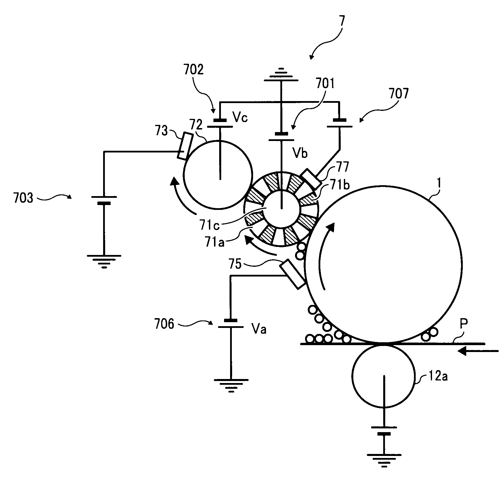
[0177]For Variation Example 2, the surfaces of the brush roller 71 and the collection roller 72 are charged with a single electrode member 79. For example, the electrode member 79 is disposed at the vicinity of the contact portion between the brush roller 71 and the collection roller 72 so as to contact both surfaces of the brush roller 71 and the collection roller 72. The electrode member 79 has an insulating member and a conductive member, such as a phosphorus bronze plate or a stainless plate, which is laid on the insulating member. The insulating member and the conductive member are connected to the power supplies 707 and 708, respectively, thereby reducing the number of components.

[0178]In the above description, although the image bearing member is d...


PUM


Abstract

A cleaning device includes a cleaning member, a collection member, an electrical field generator, and a separation member. The cleaning member has a surface capable of moving while contacting a surface of a cleaning target to remove toner on the surface of the cleaning target. The collection member has a surface capable of moving while contacting the surface of the cleaning member to collect the toner on the surface of the cleaning member. The electrical field generator generates an electrical field to move the toner from the cleaning member to the collection member. The separation member contacts the surface of the collection member to separate the toner on the surface of the collection member. The collection member has a centerline average surface roughness of not more than 0.1 μm and shows a surface hardness rank of B or higher in a steel-wool scratch test.

Description

CROSS-REFERENCE TO RELATED APPLICATIONS[0001]The present patent application claims priority under 35 U.S.C. §119 from Japanese Patent Application No. 2007-155716, filed on Jun. 12, 2007 in the Japan Patent Office, the entire contents of which are hereby incorporated herein by reference.BACKGROUND OF THE INVENTION[0002]1. Field of the Invention[0003]The present invention relates to a cleaning device; an image forming apparatus, such as a copier, a printer, or a facsimile, including the cleaning device; and a process cartridge including the cleaning device.[0004]2. Description of the Background[0005]Image forming apparatuses are used as copiers, facsimile machines, printers, and multi-functional devices combining several of the foregoing capabilities, including electrophotographic image forming apparatuses.[0006]Typically, such electrophotographic image forming apparatuses have a cleaning device to remove excess or residual toner remaining on a surface of an image bearing member after...

Claims


Application Information

Patent Timeline
Patent Type & Authority Applications(United States)
IPC IPC(8): G03G21/00
CPCG03G21/0035G03G2221/0005
Inventor NARUSE, OSAMUYANO, HIDETOSHISUGIMOTO, NAOMISUGIURA, KENJIYAMASHITA, YASUYUKI
Owner RICOH KK
Why Eureka
Try Eureka