Methods and devices for coating stents

a technology of coating stents and stents, which is applied in the direction of chemical vapor deposition coating, powder delivery, dispersed particle filtration, etc., can solve the problems of difficult treatment, adverse or even toxic side effects, and significant problem of stenosis

Inactive Publication Date: 2008-12-18
ABBOTT CARDIOVASCULAR +1
View PDF36 Cites 45 Cited by
  • Summary
  • Abstract
  • Description
  • Claims
  • Application Information

AI Technical Summary

Benefits of technology

[0014]Further embodiments of the present invention include a method of coating a stent comprising: applying a coating material to a stent mounted on a rotatable support; applying a force to an outside surfac

Problems solved by technology

Yet, restenosis remains a significant problem.
When restenosis does occur in the stented segment, its treatment can be challenging, as clinical options are more limited than for those l

Method used


Image

  • Methods and devices for coating stents
  • Methods and devices for coating stents
  • Methods and devices for coating stents

Examples


examples

[0121]The examples and experimental data set forth below are for illustrative purposes only and are in no way meant to limit the invention. The following examples are given to aid in understanding the invention, but it is to be understood that the invention is not limited to the particular materials or procedures of examples.

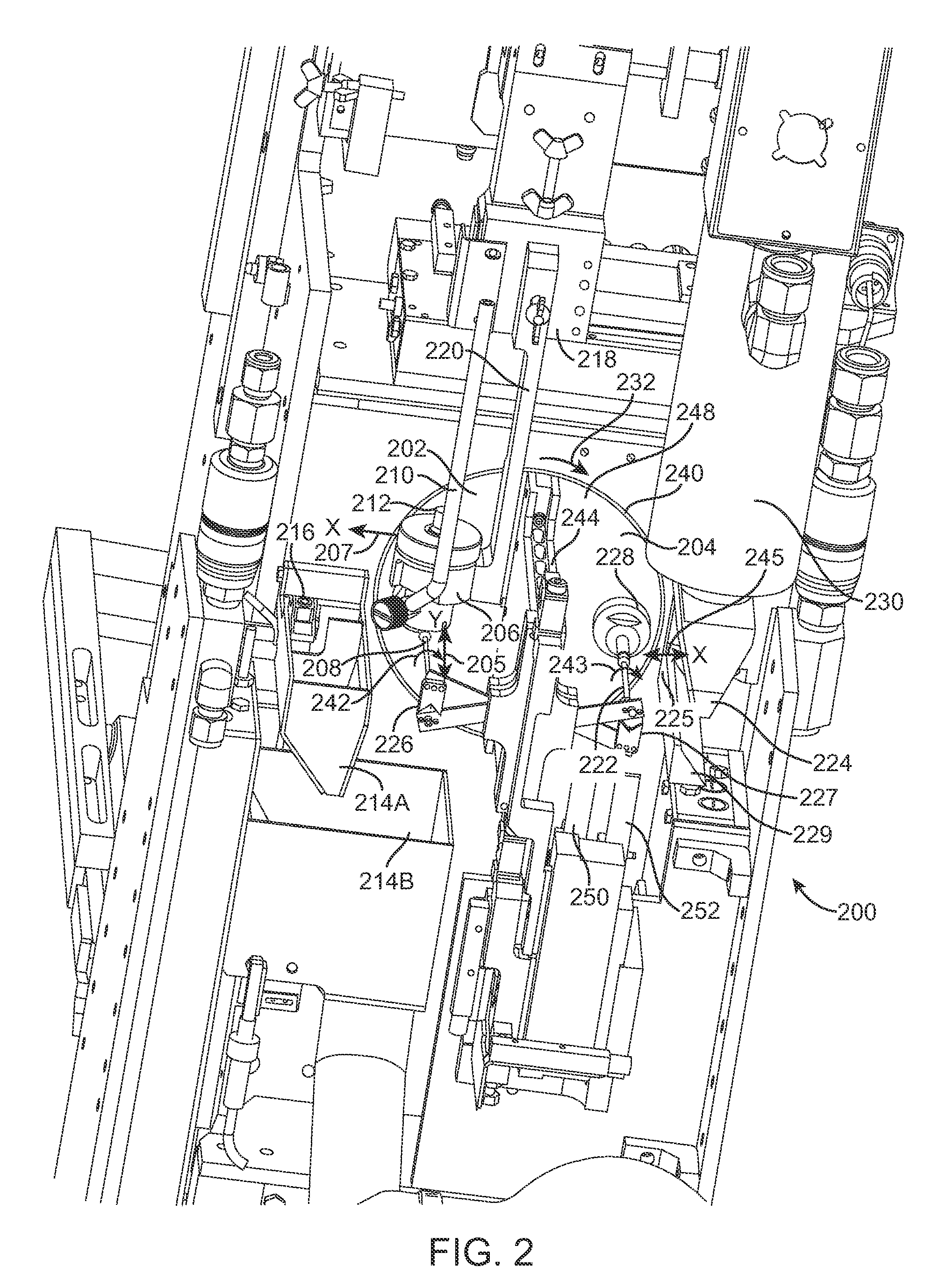
[0122]Tables 1a-d and 2a-d include spray-coating results for a coated stent using an exemplary spray coating device 200. Tables 1a-d provide coating results for an exemplary device referred to as machine 1 and Tables 2a-d provide coating results for an exemplary device referred to as machine 2. Each table represents data for a set of stents. Tables 1a-b and 2a-b are coating results of a poly(butyl methacrylate) (PBMA) primer and 1c-d and 2c-d are coating results for the poly(vinylidene fluoride-co-hexafluoropropene) (PVDF-HFP) drug coating over the primer layer. The coating weight is in μg. The relative standard deviation (RSD) is used to gauge the applied coati...


PUM

PropertyMeasurementUnit
Fractionaaaaaaaaaa
Fractionaaaaaaaaaa
Fractionaaaaaaaaaa

Abstract

Various embodiments of methods and devices for coating stents are described herein.

Description

BACKGROUND OF THE INVENTION[0001]1. Field of the Invention[0002]This invention relates to methods and devices for coating stents.[0003]2. Description of the State of the Art[0004]This invention relates to radially expandable endoprostheses, that are adapted to be implanted in a bodily lumen. An “endoprosthesis” corresponds to an artificial device that is placed inside the body. A “lumen” refers to a cavity of a tubular organ such as a blood vessel. A stent is an example of such an endoprosthesis. Stents are generally cylindrically shaped devices that function to hold open and sometimes expand a segment of a blood vessel or other anatomical lumen such as urinary tracts and bile ducts. Stents are often used in the treatment of atherosclerotic stenosis in blood vessels. “Stenosis” refers to a narrowing or constriction of a bodily passage or orifice. In such treatments, stents reinforce body vessels and prevent restenosis following angioplasty in the vascular system. “Restenosis” refers...

Claims


Application Information

Patent Timeline
IPC IPC(8): B05D1/02B05B7/00B05B13/00
CPCA61F2/91B05B13/0442B05B15/025B05C13/025B05D1/02B23K26/4065B05D1/002B05B15/55B23K2103/50Y10T137/313B23K2103/42B23K26/402
Inventor REGO, DAVIDKILCHENMANN, KURTPARK, SANG JOONHAIGHT, MARKANDREACCHI, ANTHONY S.CHEN, YUNG-MINGCURRLIN, ARNOLDO M.GARCIA, ANTONIOSCIVER, JASON VANESBECK, THOMAS DAVIDGLENN, BRYAN D.TUOHY, PATRICK A.BAILLARGEON, RICHARDGARCIA, EDWARD P.LEHNER, STEVEN E.
Owner ABBOTT CARDIOVASCULAR
Why Eureka
Try Eureka