Cardiopulmonary Resuscitation Sensor

a heart pump and sensor technology, applied in the field of sensors, can solve the problems of lack of feedback to lay first responders or professional resuscitation doctors, inadequate chest compression delivery by hand by lay responders, etc., and achieve the effects of convenient portability, self-power, and convenient portability

Active Publication Date: 2008-12-18
BOARD OF RGT THE UNIV OF TEXAS SYST +1
View PDF30 Cites 123 Cited by
  • Summary
  • Abstract
  • Description
  • Claims
  • Application Information

AI Technical Summary

Benefits of technology

[0006]The present invention provides a CPR sensor that is compact and thin so as to be readily available and easily portable, self-contained and wireless, self-powered, semi-flexible, simple and easy to use within minimal instruction and provides real-time feedback to the CPR resuscitator or provider. Moreover, the present invention will directly impact the effectiveness of CPR administered by laypersons and professionals, strengthening the second link—fast and effective CPR—in the Chain of Survival, and thus potentially reduce the fatality risk in emergency situations. The CPR sensor, which can be easily carried in a wallet or other personal belonging or clothing so that it can be located quickly during an emergency, informs the CPR provider on the characteristics of the chest compression as they are being performed. In addition, the CPR sensor permits swift and correct positioning of the helper's hands during CPR, and provides clear and concise feedback.

Problems solved by technology

It follows that the chest compressions delivery by hand by a lay responder are expected to be even more inadequate.
One of the biggest concerns in CPR is the lack of feedback to the lay first responder or professional resuscitator.
Although effective training and simulation manikins exist; small non-intrusive devices to provide real-time feedback to the resuscitator do not exist.

Method used


Image

  • Cardiopulmonary Resuscitation Sensor
  • Cardiopulmonary Resuscitation Sensor
  • Cardiopulmonary Resuscitation Sensor

Examples


first embodiment

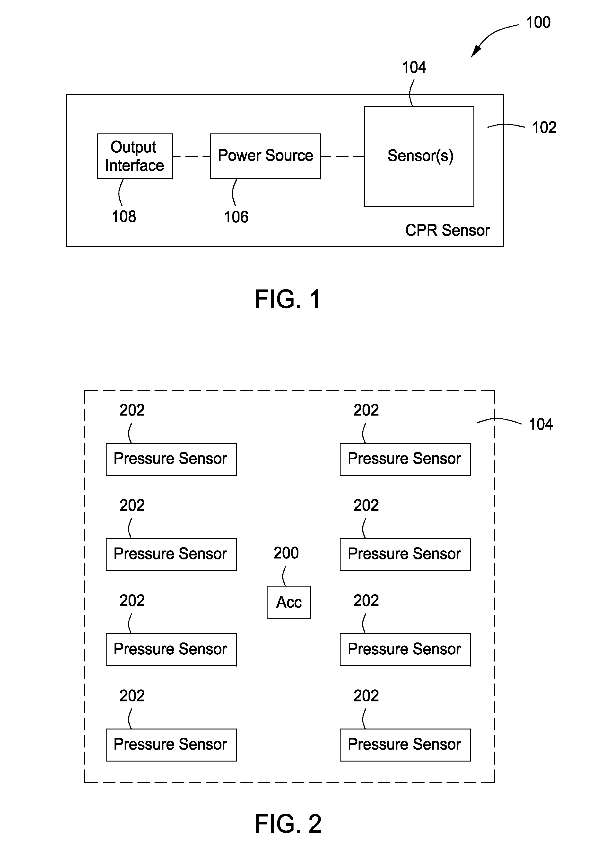
[0029]Now referring to FIG. 1, a block diagram of a CPR sensor 100 in accordance with first embodiment of the present invention is shown. The CPR sensor 100 includes a thin and substantially flat flexible substrate 102 having one or more sensor arrays 104, a power source 106 and an output interface 108, all of which are disposed on the substantially flat flexible substrate 102. The substrate 102 can be any shape (e.g., rectangular, circular, a polygon, an irregular shape that is decorative) and made from a polymer, metal film or other suitable material. Note that the substrate 102 can be rigid or semi-flexible instead of flexible. If the substrate 102 is flexible or semi-flexible, it should be able to be stretched, wrinkled or flexed without degradation of the sensors 104. The one or more sensor arrays 104 measure one or more compression characteristics (e.g., depth, force, frequency, acceleration, etc.). The sensor array 104 and output interface 108 are connected to the power sourc...

second embodiment

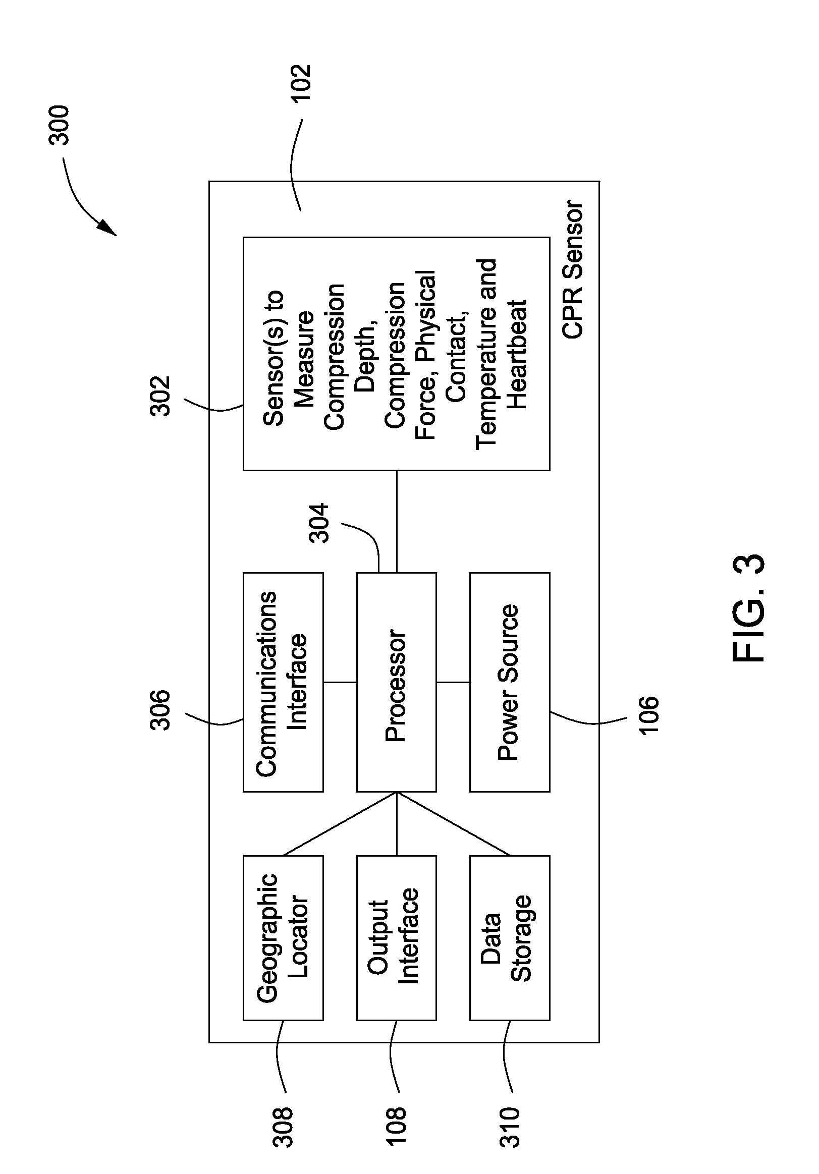
[0035]Now referring to FIG. 3, a block diagram of a CPR sensor 300 in accordance with the present invention is shown. The CPR sensor 300 includes a thin and substantially flat flexible substrate 102 having one or more sensor arrays 302, a processor or analog circuit 304, a power source 106, a communications interface 306, a geographic locator 308, an output interface 108 and a data storage 310, all of which are disposed on the substantially flat flexible substrate 102. The substrate 102 can be any shape (e.g., rectangular, circular, a polygon, an irregular shape that is decorative) and made from a polymer, metal film or other suitable material. Note that the substrate 102 can be rigid or semi-flexible instead of flexible. If the substrate 102 is flexible or semi-flexible, it should be able to be stretched, wrinkled or flexed without degradation of the sensors 302. The geographic locator can be a GPS receiver, wireless communications device or other wireless location device. A protec...

third embodiment

[0040]Referring now to FIG. 4, an exploded view of a CPR sensor 400 in accordance with the present invention is shown. The CPR sensor 400 includes an upper protective layer 402, a lower protective layer 404, a thin and substantially flat flexible substrate 406 and an energy producing layer 408 (e.g., a layer of piezoelectric film or other means for energy harvesting during compressions). The substrate 406 can be any shape (e.g., rectangular, circular, a polygon, an irregular shape that is decorative) and made from a polymer, metal film or other suitable material. The thin and substantially flat flexible substrate 406 and an energy producing layer 408 are both disposed between the upper protective layer 402 and the lower protective layer 404. The upper protective layer 402 and lower protective layer 404 are semi rigid plastic films, but other materials can also be used. Upper protective layer can also be made of a transparent or semi-transparent material. If the upper protective laye...


PUM


Abstract

The present invention provides a CPR sensor that includes a thin and substantially flat flexible substrate having one or more sensor arrays, a power source, an output interface and a processor or analog circuit, all of which are disposed on the substantially flat flexible substrate. The substrate can be any shape (e.g., rectangular, circular, a polygon, an irregular shape that is decorative) and made from a polymer, metal film or other suitable material. Note that the substrate can be rigid or semi-flexible instead of flexible. A protective layer may cover the sensor array, the power source, and the processor or analog circuit. Alternatively, a protective covering can be used to encapsulate the device. The one or more sensor arrays measure one or more of the following compressions characteristics: compression depth, compression force, compression frequency and compression acceleration.

Description

CROSS-REFERENCE TO RELATED APPLICATIONS[0001]This patent application is related to U.S. provisional patent application No. 60 / 944,479 filed on Jun. 15, 2007 and entitled “Thin Flexible Sensor” which is hereby incorporated by reference in its entirety.FIELD OF THE INVENTION[0002]The present invention relates generally to the field of sensors and, more particularly, to a cardiopulmonary resuscitation sensor.BACKGROUND OF THE INVENTION[0003]Cardiopulmonary Resuscitation (CPR) is an emergency procedure consisting of external cardiac massage and artificial respiration that constitutes the first treatment for a person who has collapsed, has no pulse and has stopped breathing. CPR treatment attempts to restore circulation of the blood and prevent death or brain damage due to lack of oxygen. Survival from cardiac arrest within 4 minutes of collapse is primarily dependent on rapid defibrillation, but thereafter maintaining coronary and cerebral perfusion of at least 25% of baseline is essent...

Claims


Application Information

Patent Timeline
Patent Type & Authority Applications(United States)
IPC IPC(8): A61H31/00G01P15/09
CPCA61H31/005A61H31/006A61H31/007A61H2201/5007A61H2201/501A61H2201/5012A61H2201/5043A61H2201/5048A61H2201/5061A61H2201/5064A61H2201/5071A61H2201/5084A61H2201/5097A61H2230/04A61H2230/50G09B23/288
Inventor CELIK-BUTLER, ZEYNEPPRIEST, JOHN W.CASON, CAROLYN L.MANCINI, MARY E.MORALLEE, KENNETH GEORGEFOSSAN, HELGE
Owner BOARD OF RGT THE UNIV OF TEXAS SYST
Why Eureka
Try Eureka