Injection Device

a technology of injection device and lever, which is applied in the direction of intravenous device, infusion needle, ampoule syringe, etc., can solve the problems of affecting the reliability of the unlatching mechanism itself, difficult delatching, and relatively high delatching for

Active Publication Date: 2008-12-18
CILAG GMBH INT
View PDF101 Cites 15 Cited by
  • Summary
  • Abstract
  • Description
  • Claims
  • Application Information

AI Technical Summary

Benefits of technology

[0054]in which the flexible arm is prevented from disengaging from the drive surface until the drive has been advanced to a nominal release position, whereupon the flexible arm disengages from the drive surface, allowing the actuator to move relative to the drive and thus releasing the syringe from the action of the actuator, whereupon the biasing means restores the syringe to its retracted position.
[0055]The use of a stop to restrain the flexible arm and prevent its disengagement from the drive surface means that it need not be made as stiff as was the case with FIG. 1. Hence a more flexible material can be used and the shortcomings associated with the arrangement of FIG. 1 are avoided.

Problems solved by technology

This requirement introduces manufacturing difficulties and may also affect the reliability of the unlatching mechanism itself.
This deals with one problem of using flexible arms under tension, which can be difficult to delatch, needing a relatively high delatching force.

Method used


Image

  • Injection Device
  • Injection Device
  • Injection Device

Examples


Embodiment Construction

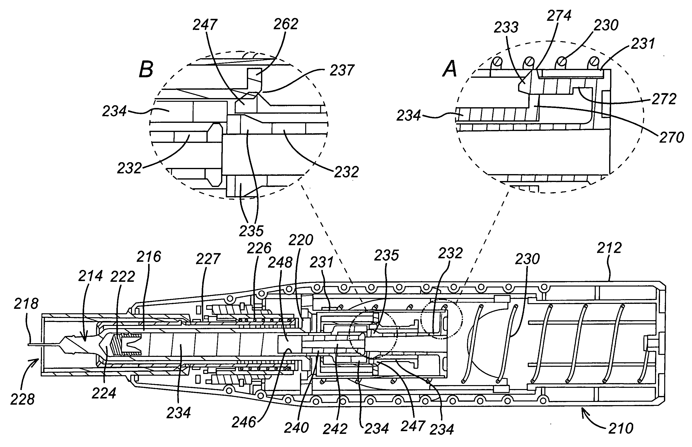
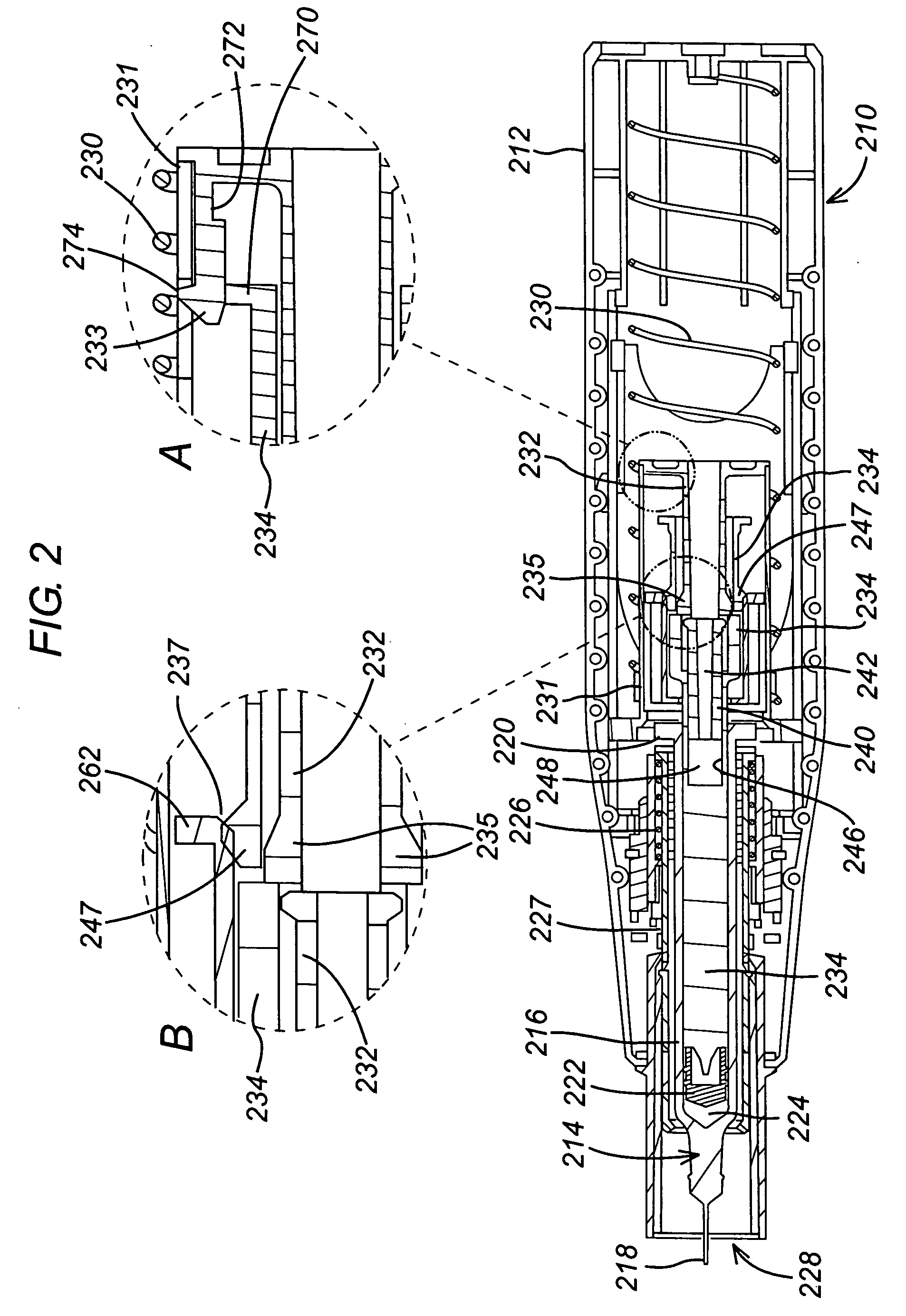
[0061]FIG. 2 shows an injection device 210 in which a housing 212 contains a hypodermic syringe 214. The syringe 214 is again of conventional type, including a syringe body 216 terminating at one end in a hypodermic needle 218 and at the other in a flange 220, and a rubber bung 222 that constraints a drug 224 to be administered within the syringe body 216. The conventional plunger that would normally be connected to the bung 222 and used to discharge the contents of the syringe 214 manually, has been removed and replaced with a multi-component drive element as will be described below. Whilst the syringe illustrated is again of hypodermic type, this need not necessarily be so. As illustrated, the housing includes a return spring 226 that biases the syringe 214 from an extended position in which the needle 218 extends from aperture 228 in the housing 212, to a retracted position in which the hypodermic needle 218 is contained within the housing 212. The return spring 226 acts on the s...


PUM


Abstract

An injection device (210) is described. A housing (212) receives a syringe and includes a return spring (226) for biasing the syringe from an extended position in which its needle (218) extends from the housing (212) to a retracted position in which the it does not. A drive spring (230) acts on a first drive element (232) and a second drive element (234) acts upon the syringe to advance it from its retracted position to its extended position and discharge its contents through the needle. The first drive element (232) is capable of movement relative to the second (234) once a nominal decoupling position has been reached. A release mechanism is activated when the first drive element (234) is further advanced to a nominal release position, to release the syringe (214) from the action of the drive spring (230), whereupon the return spring (226) restores the syringe (214) to its retracted position. Decoupling of the drive elements is achieved with a particular form of releasable drive coupling using two pairs of overlying flexible arms (235, 247). A particular form of release mechanism that also uses flexible arms (233) is also envisaged.

Description

BACKGROUND TECHNOLOGY[0001]The present invention relates to a releasable coupling for use in an injection device of the type that receives a syringe, extends it, discharges its contents and then retracts it automatically. Devices of this general description are shown in WO 95 / 35126 and EP-A-0 516 473 and tend to employ a drive spring and some form of release mechanism that releases the syringe from the influence of the drive spring once its contents are supposed to have been discharged, to allow it to be retracted by a return spring.[0002]Because of the stack-up of tolerances of the various components of the device, a certain margin of safety must be built into the activation of the release mechanism, to ensure that it is effective. The consequence of underestimating the safety margin is that the release mechanism may fail to operate even once the syringe contents have been discharged, which is unsatisfactory in a device that is supposed to retract automatically, particularly for se...

Claims


Application Information

Patent Timeline
Patent Type & Authority Applications(United States)
IPC IPC(8): A61M5/20A61M5/32
CPCA61M5/2033A61M2005/3261A61M5/3204A61M5/20A61M5/315A61M5/32A61M5/178A61M5/326A61M2005/202A61M2005/206A61M5/24
Inventor HARRISON, NIGEL
Owner CILAG GMBH INT
Why Eureka
Try Eureka