Computer-assisted joint analysis using surface projection

a surface projection and computer-assisted technology, applied in image data processing, diagnostics, sensors, etc., can solve the problems of computational complexity, difficult visualization, easy comprehensibility, etc., and achieve the effect of facilitating visualization of data

Inactive Publication Date: 2008-12-18
BRAINLAB
View PDF0 Cites 65 Cited by
  • Summary
  • Abstract
  • Description
  • Claims
  • Application Information

AI Technical Summary

Benefits of technology

[0012]In other words, the method in accordance with the invention reduces the processing problem for the obtained imaging data of the joint elements to the two-dimensional plane, namely by projecting the required imaging data onto the reference area. Once the characteristic data for the joint has been processed in this way, it is possible to ascertain particular deficiencies or states on the joint in a robust, quick and very generally valid way, by relatively simple observations of the projected images. Also, the two-dimensional nature of the resulting data facilitates visualizing the data, i.e., for visually outputting the data for those who are planning a treatment.

Problems solved by technology

Such analyses may be computationally elaborate and it may be difficult to visualize the result in an easily comprehensible form.
It may be difficult, however, to show where bone interferences will occur in particular joint positions.
For treatments to correct the bone surfaces, specific features from the obtained three-dimensional image data can be used, however, this use may lead to imprecise surgery or incision planning.
The interaction with the three-dimensional data in a computer-assisted joint analysis also may make the corresponding algorithms used relatively slow, unstable, and problematic with respect to the soft tissue structures in the joint region.

Method used


Image

  • Computer-assisted joint analysis using surface projection
  • Computer-assisted joint analysis using surface projection
  • Computer-assisted joint analysis using surface projection

Examples


Embodiment Construction

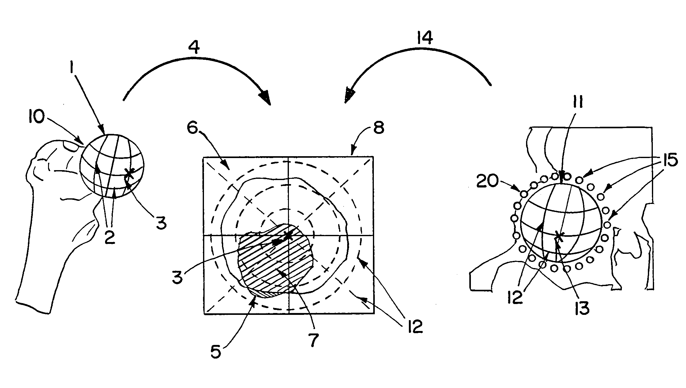
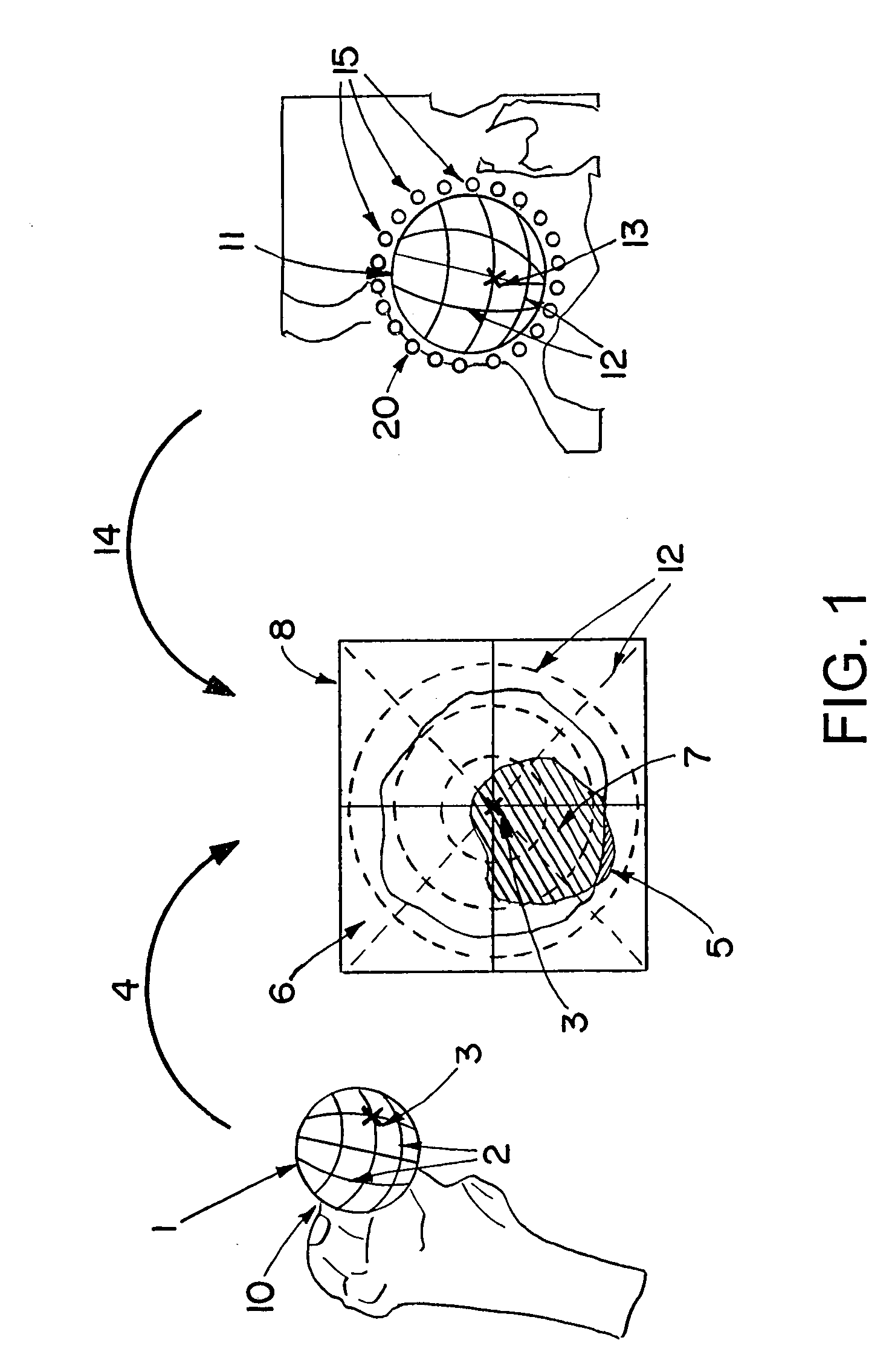
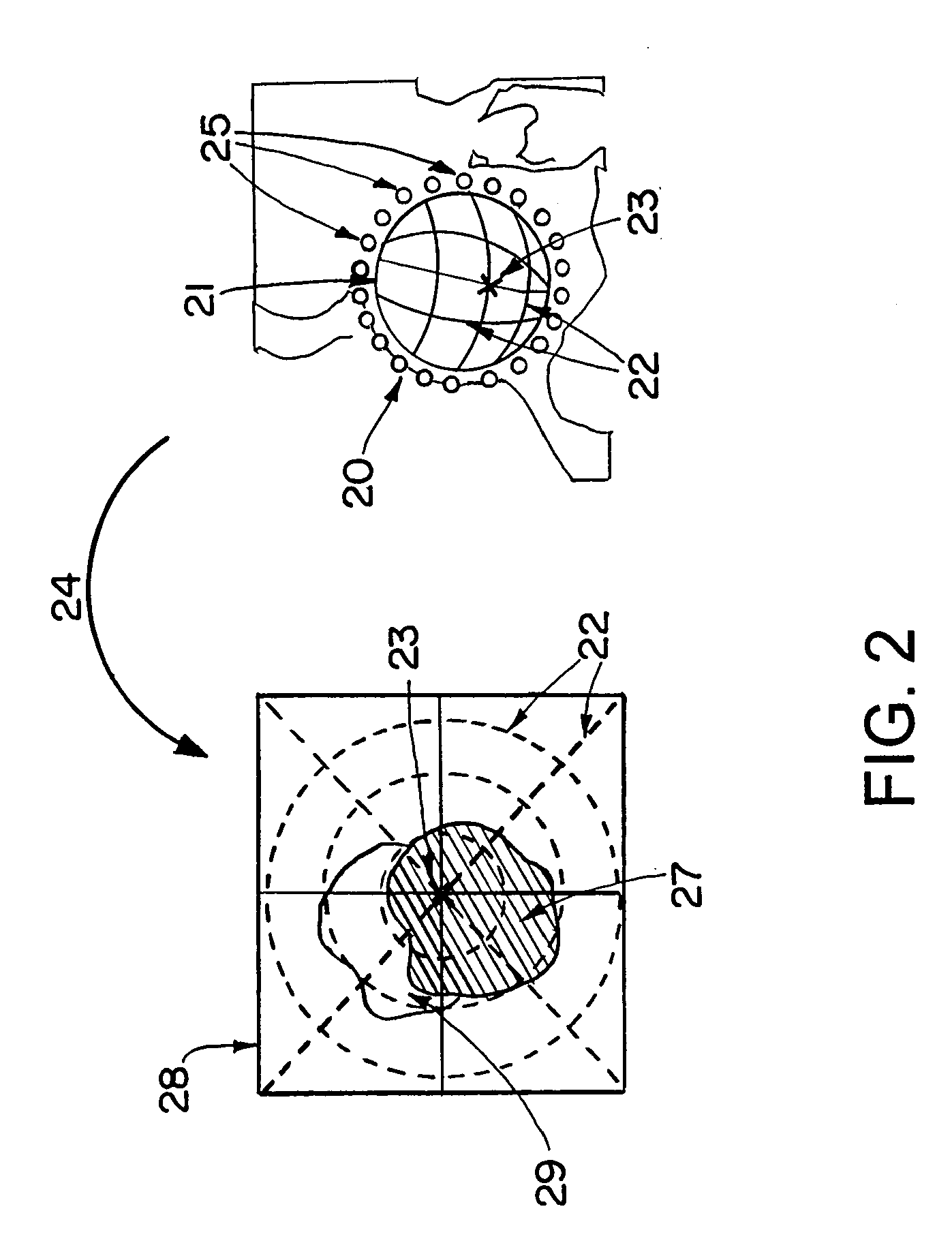
[0017]The objects (the joint elements) processed in accordance with the invention can form a three-dimensional image or are configured such that a three-dimensional image can be produced. The three-dimensional image can be, for example, a surface model, a voxel model, or the like. In medical applications, the three-dimensional image can be produced by segmenting the relevant objects in a CT, MR, or x-ray volume data set. Alternatively, such three-dimensional images can be provided from particular types of three-dimensional models, for example from CAD models for known implants (or from body atlases or other) wherein the models can be adapted to the actual size.

[0018]A mathematical model of the joint motion helps in calculating idealized motion surfaces that can be used to calculate critical regions. Idealized motion surfaces can be calculated for each individual object. The idealized motion surfaces also can be referred to herein as “border areas,” since they represent the border li...


PUM


Abstract

A system and method for computer-assisted joint analysis, wherein the joint elements in a three-dimensional imaging data set are segmented and then projected onto a two-dimensional or three-dimensional reference area for interference analysis and surgical planning.

Description

RELATED APPLICATION DATA[0001]This application claims priority of U.S. Provisional Application No. 60 / 951,287 filed on Jul. 23, 2007, and EP 07 110 355.0 filed on Jun. 15, 2007, which are incorporated herein by reference in their entirety.FIELD OF THE INVENTION[0002]The invention relates to a system and method for computer-assisted joint analysis. Joint analysis includes many different joint determinations and evaluations including: detecting bone interferences in the joint; planning for joint treatment methods; and shape analysis for particular joint elements.BACKGROUND OF THE INVENTION[0003]To perform a computer-assisted joint analysis, volume image data sets (for example, CT, MR or x-ray volume image data sets) of the joint environment may be produced using a medical imaging method. The actual, three-dimensional contour and shape of joint elements (for example, bones) can be determined using computer-assisted image processing. If image data sets of the joint region are captured, ...

Claims


Application Information

Patent Timeline
Patent Type & Authority Applications(United States)
IPC IPC(8): A61B19/00A61B17/58
CPCG06T7/0012G06T2207/30008
Inventor HAIMERL, MARTINTUMA, GREGORSCHINDLER, FLORIANFRICKE, MARK
Owner BRAINLAB
Why Eureka
Try Eureka