Spring manufacturing apparatus

a manufacturing apparatus and spring technology, applied in manufacturing tools, forging presses, hammering/pressing machines, etc., can solve the problems of difficult to arrange the large number of turrets around the quill in view of the size of the turret, interfere with the formation of the wire rod into a desired spring shape, etc., to achieve good precision, accurate adjustment of the relative position of the quill, and good precision

Active Publication Date: 2008-12-25
SHINKOU KIKAI INDS
View PDF9 Cites 8 Cited by
  • Summary
  • Abstract
  • Description
  • Claims
  • Application Information

AI Technical Summary

Benefits of technology

[0014]The present invention is proposed in view of the above, and aims to provide a spring manufacturing apparatus in which an opening is formed in a supporting body including at least one of a movable body which moves in an X-axis direction, a movable body which moves in a Y-axis direction, or a movable body which moves in a Z-axis direction of a XYZ orthogonal coordinate system representing a moving region of a wire rod fed from a wire rod feeding unit as the Z-axis, a quill is arranged in the opening, and a tool holder for holding the processing tool for processing the wire rod to the spring is arranged on the supporting body, so that the supporting body arranged at the vicinity of the quill is moved to accurately adjust the relative position of the quill and the processing tool to manufacture a spring of good precision, and a desired spring is manufactured and miniaturization is achieved while avoiding restrictions on the length of the wire rod that can be fed when manufacturing one spring, the folding or the rotation of the wire rod, and the like, and furthermore, a number of tool holders can be arranged at the vicinity of the quill, and the reactive force generated when the processing tool contacts the wire rod is absorbed by the entire supporting body so that durability of the supporting body is enhanced, and a plurality of tool holders are arranged on the supporting body so that two reactive forces that generate when the two processing tools abut against each other to process the wire rod are canceled out at the supporting body, whereby the position of the supporting body is prevented from being biased.
[0015]In the present invention, it is an object to provide a sprig manufacturing apparatus accurately adjusting the relative position of the quill and the processing tool to manufacture a spring of good precision while achieving miniaturization and capable of moving the movable unit in the X-axis (or Y-axis) direction to select a necessary processing tool from the plurality of processing tools attached to one tool holder, by providing a slide for sliding the tool holder towards and away from the quill and means for controlling the movement of the slide and the supporting body, so that the movement of the slide and the movement of the supporting body are cooperatively operated to move the processing tool held on the tool holder at high speed, thereby accurately adjusting the relative position of the quill and the processing tool.
[0016]In the present invention, it is an object to provide a spring manufacturing apparatus capable of avoiding a portion of the wire rod processed to a spring from being contact with the processing tool, and preventing the avoided wire rod from contacting the quill, by coupling a plurality of driving sources respectively to the wire rod feeding unit and the quill by means of a transmission member, so that the wire rod feeding unit and the quill are rotated about the axial core of the wire rod to rotate the wire rod, avoiding a portion of the wire rod processed to a spring from being contact with the processing tool, and preventing the avoided wire rod from contacting the quill.
[0017]Furthermore, in the present invention, it is an object to provide a spring manufacturing apparatus capable of accurately adjusting the relative position of the quill and the processing tool to manufacture a spring of good precision while achieving miniaturization and capable of moving the movable unit in the X-axis (or Y-axis) direction to select a necessary processing tool from the plurality of processing tools attached to one tool holder, by providing a movable unit that moves in the X-axis direction and the Y-axis direction on the supporting body which moves in the Z-axis direction, and providing a tool holder on the movable unit, while arranging the movable unit and the tool holder on the Y-axis (or X-axis) through the supporting body, to hold plurality of tools in the X-axis (Y-axis) direction at the quill side portion of the tool holder, thereby moving the movable unit and the supporting body arranged at the vicinity of the quill.
[0018]In the present invention, it is an object to provide a spring manufacturing apparatus capable of accurately adjusting the relative position of the quill and the processing tool to manufacture a spring of good precision, by coupling a plurality of driving sources respectively to a movable member having two movable members by means of a transmission member, thereby moving each movable member in the X-axis direction or the Y-axis direction.
[0019]Moreover, in the present invention, it is an object of the present invention to provide a spring manufacturing apparatus capable of avoiding a portion of the wire rod processed to a spring from contacting the processing tool, and preventing the avoided wire rod from contacting the quill, by coupling a plurality of driving sources respectively to the wire rod feeding unit and the quill by means of a transmission member, thereby rotating the wire rod feeding unit and the quill about the axial core of the wire rod to rotate the wire rod.

Problems solved by technology

The distortion of the entire wire rod feeding unit generates a bias of a non-negligible size for processing of the wire rod, and may interfere the formation of the wire rod into a desired spring shape.
Therefore, the shape of the formable spring is limited due to restrictions on the length of the wire rod that can be fed when manufacturing one spring, the folding or the rotation of the wire rod, and the like.
A great number of turrets need to be arranged around the quill in order to radially arrange a great number of processing tools around the quill, but it is difficult to arrange the great number of turrets around the quill in view of the size of the turret.
Furthermore, when abutting the two processing tools respectively arranged on the two movable tables in processing the wire rod, the reactive force generated by the processing acts as a force for separating the two movable tables from each other, and thus tends to lower the durability of the movable table.

Method used


Image

  • Spring manufacturing apparatus
  • Spring manufacturing apparatus
  • Spring manufacturing apparatus

Examples


first embodiment

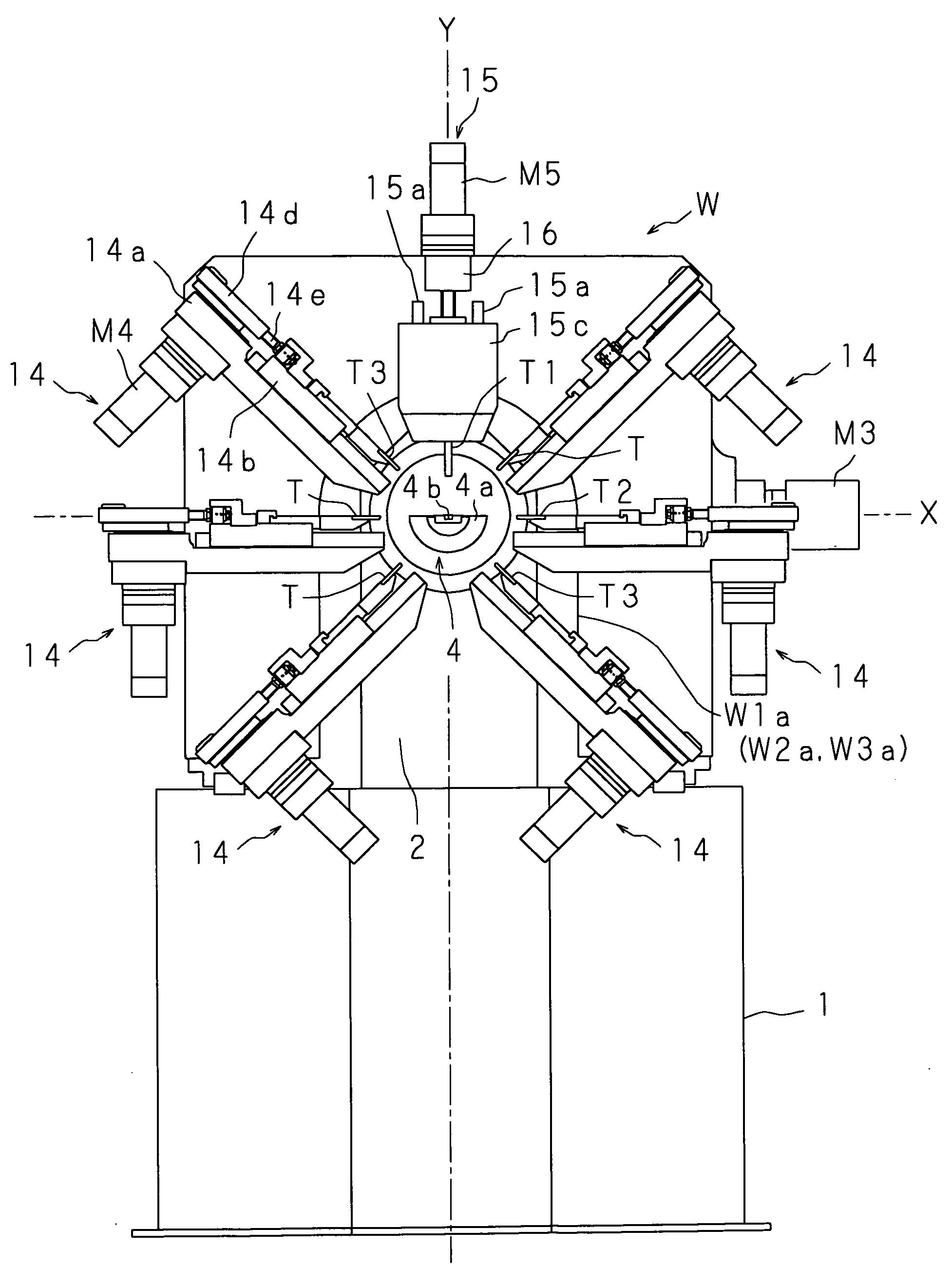
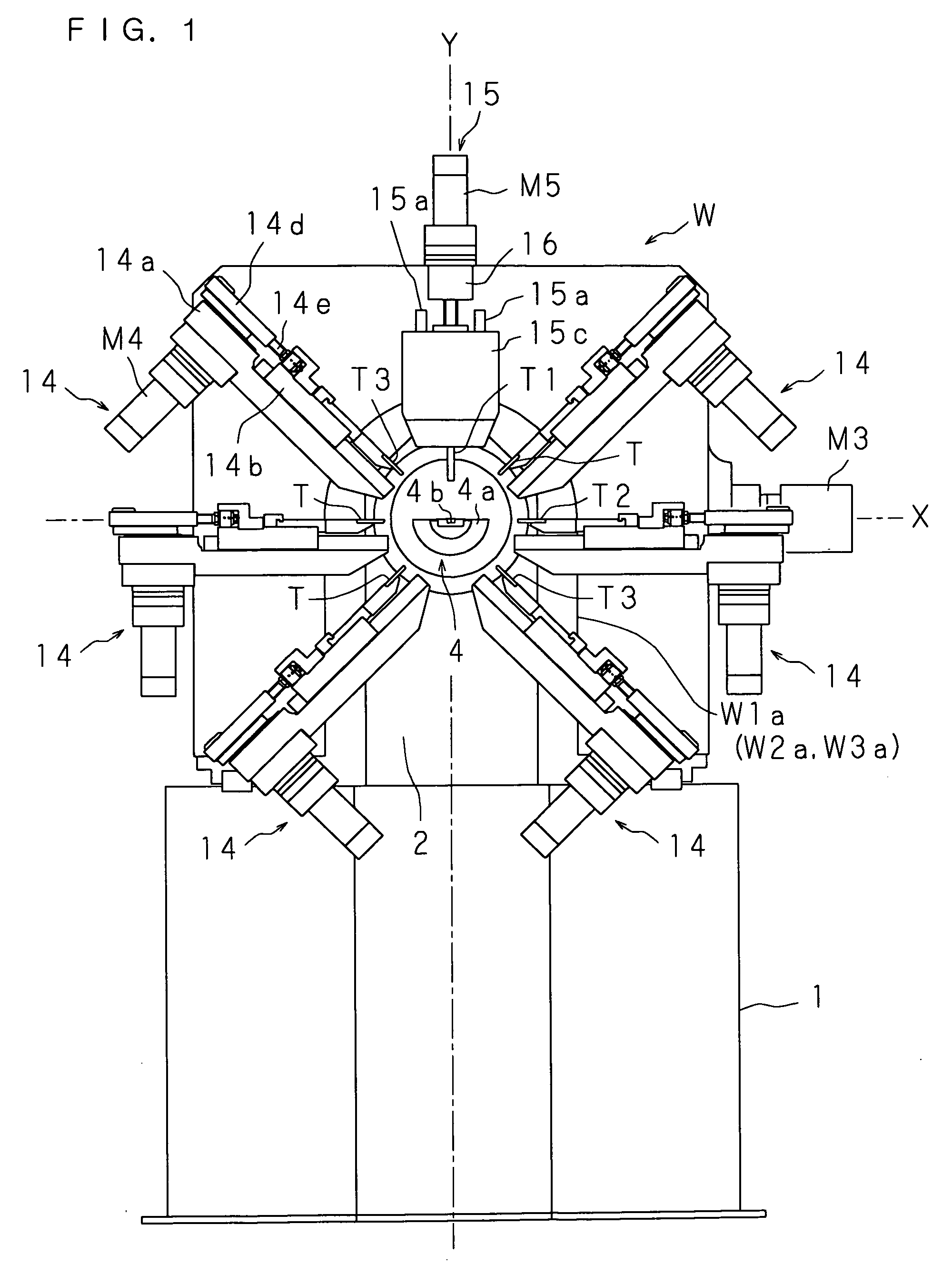
[0085]The present invention will be described in detail with reference to drawings showing a spring manufacturing apparatus according to a first embodiment. FIG. 1 is a schematic front view of a spring manufacturing apparatus, FIG. 2 is a schematic side view of the spring manufacturing apparatus, FIG. 3 is a frame format front perspective view showing a sliding member and a rail arranged on a movable plate, and FIG. 4 is a schematic plan partial cross sectional view of the spring manufacturing apparatus.

[0086]With reference to the figures, reference numeral 1 is a box shaped base of the spring manufacturing apparatus, wherein a supporting plate 2 for supporting a quill 4 to be hereinafter described is arranged in an upstanding manner on the upper surface of the base 1 near the center towards the front surface face of the base 1. A wire rod feeding unit 3 for feeding the wire rod is arranged on the rear surface side of the supporting plate 2. The wire rod feeding unit 3 includes two ...

second embodiment

[0134]The present invention will now be described in detail with reference to the drawings showing a spring manufacturing apparatus according to a second embodiment. FIG. 23 is a schematic side view of the spring manufacturing apparatus according to the second embodiment. FIG. 24 is a schematic plan partial cross sectional view of the spring manufacturing apparatus.

[0135]A supporting body W including two movable plates W2, W3 and an attachment plate 50 attached with the movable plates W2, W3 is arranged at the vicinity of a supporting plate 2 on the upper surface of a base 1. An opening 50a cutout in an arch shape is opened in the attachment plate 50 from the lower center portion to the center part of the attachment plate 50. The attachment plate 50 is arranged to surround the wire rod feeding unit 3 with the opening 50a. The movable plates W2, W3 are attached in order on the front surface side of the attachment plate 50. As described above, the movable plate W2 and the movable plat...

third embodiment

[0142]The present invention will now be described in detail with reference to the drawings showing a spring manufacturing apparatus according to a third embodiment. FIG. 25 is a schematic side view of the spring manufacturing apparatus according to the third embodiment. FIG. 26 is a schematic plan partial cross sectional view of the spring manufacturing apparatus.

[0143]A supporting body W including the movable plate W1 is arranged on the upper surface of a base 1. An opening W1a cutout in an arch shape is opened in the movable plate W1 from the lower center portion to the center part of the movable plate W1. The movable plate W1 is arranged to surround a quill 4 with the opening W1a. As described above, the movable plate W1 is configured to move along the Z-axis.

[0144]Six crank slides 14, 14, . . . and a ball screw slide 15 are radially arranged with the quill 4 as the center on the front surface of the movable plate W1. A folding tool T2 and cutters T3, T3 held by the crank slides ...


PUM

PropertyMeasurementUnit
reactive forceaaaaaaaaaa
sizeaaaaaaaaaa
lengthaaaaaaaaaa

Abstract

A spring manufacturing apparatus includes a supporting body which moves in X, Y, and Z-axes directions of a XYZ orthogonal coordinate system representing a moving direction of a wire rod fed from a wire rod feeding unit as a Z-axis. The supporting body is formed with an opening in which the quill is arranged. The supporting body further includes a tool holder for holding a processing tool for processing the wire rod to a spring. The supporting body arranged at the vicinity of the quill is moved to accurately adjust the relative position of the quill and the processing tool, thereby manufacturing a desired spring.

Description

CROSS-REFERENCE OF RELATED APPLICATIONS[0001]This Nonprovisional application claims priority under 35 U.S.C. §119(a) on Patent Application No. 2007-163086 filed in Japan on Jun. 20, 2007, the entire contents of which are hereby incorporated by reference.BACKGROUND[0002]1. Field of the Invention[0003]The present invention relates to a spring manufacturing apparatus capable of manufacturing a spring with good precision, in particular to a spring manufacturing apparatus capable of manufacturing a spring with good precision by moving a processing tool for processing a wire rod to a spring, instead of moving the wire rod feeding unit, in at least one direction of XYZ orthogonal three-axes directions in which a moving region of the wire rod fed from a wire rod feeding unit is represented as a Z axis.[0004]2. Description of Related Art[0005]Generally, a quill type spring manufacturing apparatus includes a wire rod feeding unit with a wire rod feeding roller for feeding a wire rod, a semi-c...

Claims


Application Information

Patent Timeline
Patent Type & Authority Applications(United States)
IPC IPC(8): B21F35/02
CPCY10T29/5187B21F3/02
Inventor TSURITANI, KATSUHIDEUCHIDA, NORIHIRO
Owner SHINKOU KIKAI INDS
Why Eureka
Try Eureka