Linearly Driven and Air-Cooled Boring and/or Percussion Hammer

a percussion hammer and linear drive technology, which is applied in the direction of boring/drilling equipment, portable percussive tools, drilling machines and methods, etc., can solve the problems that the pneumatic spring hammer mechanism produces heat that has to be dissipated, and achieves less mechanical stress, reliable operation, and small loss

Inactive Publication Date: 2008-12-25
WACKER NEUSON SE
View PDF8 Cites 19 Cited by
  • Summary
  • Abstract
  • Description
  • Claims
  • Application Information

AI Technical Summary

Benefits of technology

[0016]In a particularly advantageous specific embodiment of the present invention, the drive element, the runner, and the pump element form a constructive unit. In particular, these constructive elements can be connected to one another in one piece, so that the movement of the runner can be transmitted without loss to the drive element and to the pump element. The drive element and the pump element are then compelled to follow the movement of the runner.
[0017]In a specific embodiment of the present invention, the movement of the drive element can be transmitted to the pump element via a mechanical coupling, a hydraulic coupling, or a pneumatic coupling. For example, between the drive element and the pump element there may run a Bowden cable or a hydraulic line in order to transmit the movement of the drive element to the pump element with as little loss as possible. In this variant, it is not necessary for the drive element and the runner to form a constructive unit with the pump element. Rather, the pump element can then also be situated at a different location in the hammer.
[0018]In a particularly advantageous further development, the pump element is situated in an area of the hammer that is decoupled from the percussion mechanism in terms of vibration. The percussion mechanism and the linear drive produce a significant amount of vibration due to the oscillating movement of the movable elements and the impact action of the percussion element. From the prior art, many solution strategies are known for isolating these vibrations e.g. from a handle of the hammer, and to protect the operator from damaging vibrations. Correspondingly, in almost all hammers it is known to decouple at least a partial area from the percussion mechanism in terms of vibration. The situation of the pump element in this vibration-decoupled area has the advantage that the pump element and the other components of the air-conveying device are subject to less mechanical stress, so that more reliable functioning can be achieved.

Problems solved by technology

However, during operation of the hammer the linear drive and the pneumatic spring hammer mechanism produce heat that has to be dissipated.

Method used


Image

  • Linearly Driven and Air-Cooled Boring and/or Percussion Hammer
  • Linearly Driven and Air-Cooled Boring and/or Percussion Hammer
  • Linearly Driven and Air-Cooled Boring and/or Percussion Hammer

Examples


Embodiment Construction

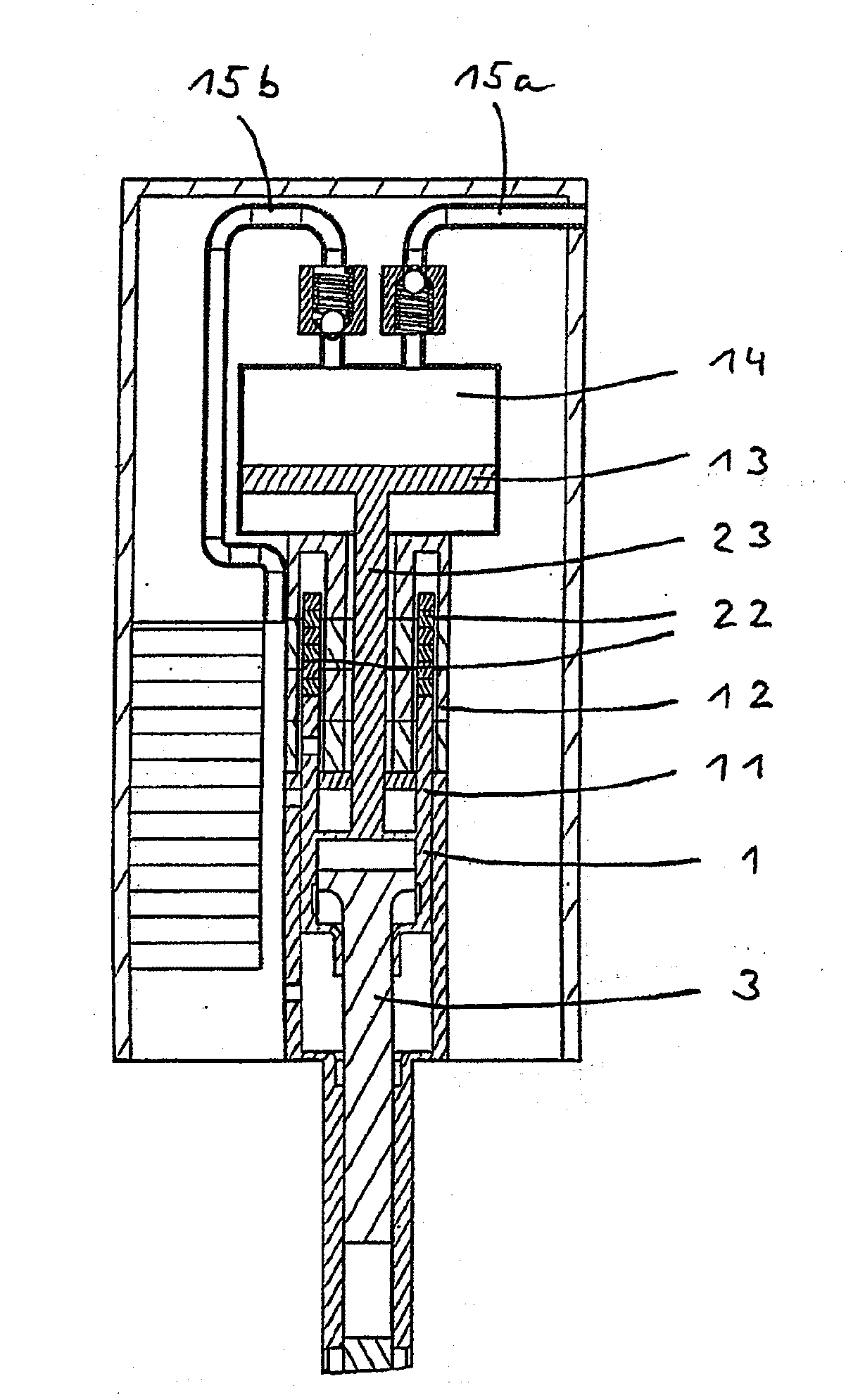
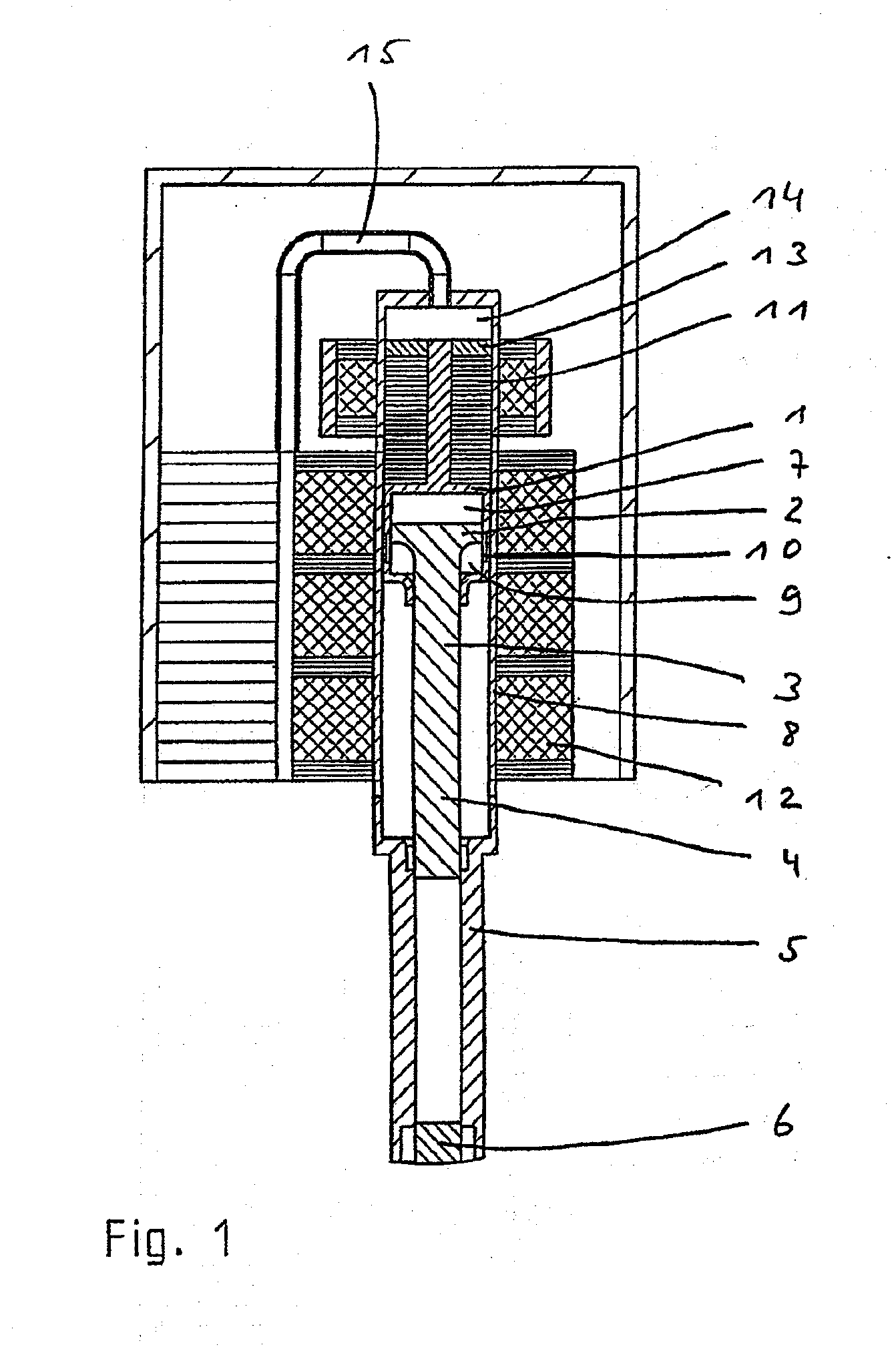
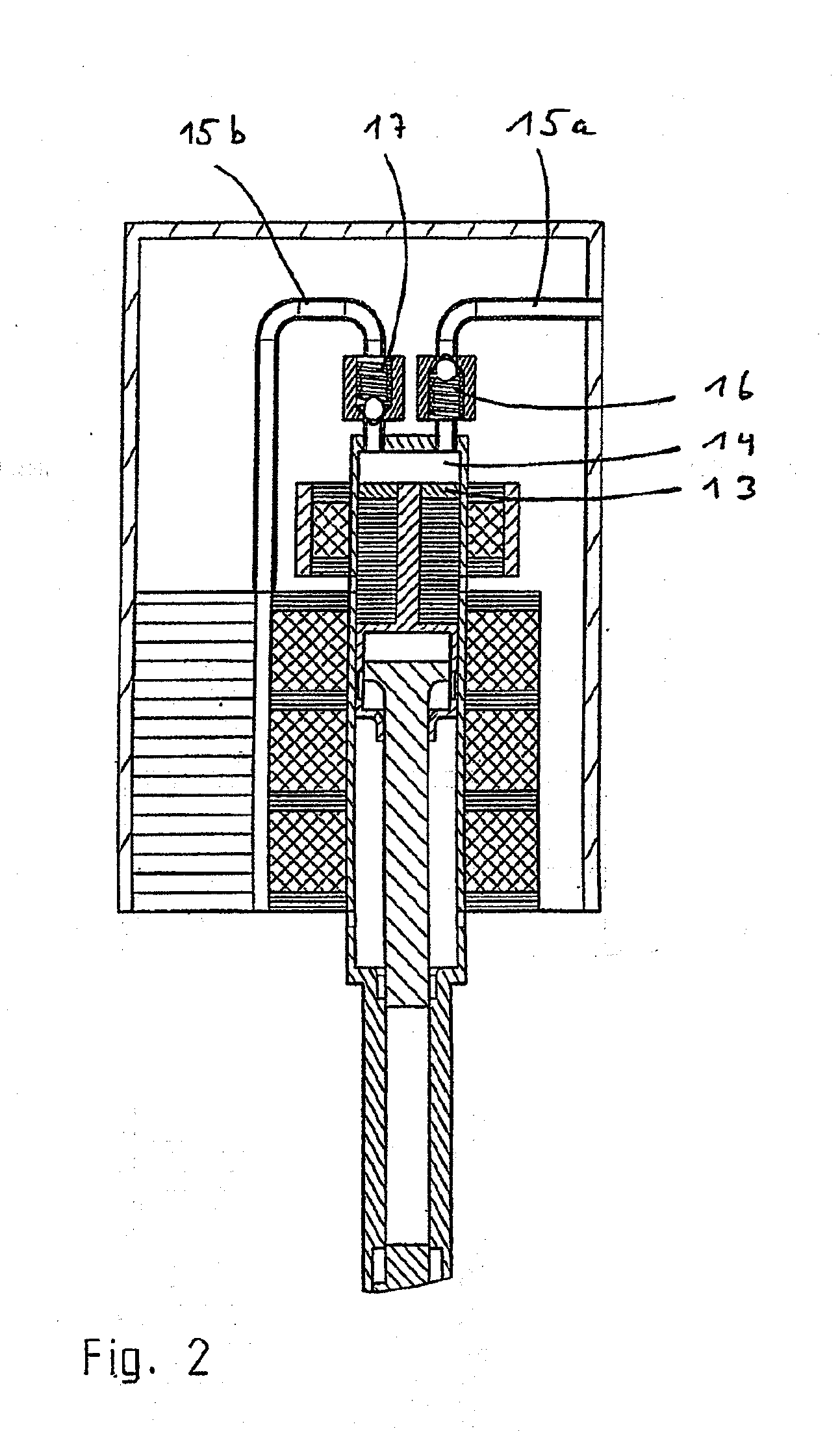
[0041]FIGS. 1 to 8 show various specific embodiments of the hammer according to the present invention in a greatly simplified sectional representation. In particular, known components such as e.g. handles and electrical terminals are omitted, because they do not relate to the present invention.

[0042]FIG. 1 shows a first specific embodiment of the present invention having a pneumatic spring hammer mechanism driven by an electrodynamic linear drive.

[0043]The pneumatic spring hammer mechanism has, as drive element, a drive piston 1 that surrounds a piston head 2 of a percussion piston 3 that acts as a percussion element. Shaft 4 of percussion piston 3 runs in a percussion piston guide 5, and can, in its frontmost position, strike a tool end 6. Instead of tool end 6, an intermediate header can also be provided in a known manner.

[0044]Between drive piston 1 and percussion piston 3, a hollow space is formed in which a first air spring 7 acts as a coupling device. When there is a forward m...


PUM

PropertyMeasurementUnit
elasticaaaaaaaaaa
movementaaaaaaaaaa
areaaaaaaaaaaa

Abstract

A boring and/or percussion hammer comprises an electrodynamic linear drive and a pneumatically damped percussion mechanism which is provided with a drive piston driven by the linear drive during the reciprocating movement thereof, an impact piston and a pneumatic spring arranged between the drive and impact pistons. An air-supply device comprises a pumping element, which is linearly forth and back movable for generating airflow. The pumping element is connected to the drive piston in such a way that the movement thereof is transmitted to said pumping element, thereby the cooling air is transported by an air channel for cooling heat generated elements.

Description

BACKGROUND OF THE INVENTION[0001]1. Field of the Invention[0002]According to the preamble of claim 1, the present invention relates to a boring and / or percussion hammer having an electrodynamic linear drive.[0003]2. Description of the Related Art[0004]Boring and / or percussion hammers (referred to as “hammers” hereinafter) are standardly driven by electric motors in which a rotor rotates a drive shaft. In order to cool the motor and the percussion mechanism provided in the hammer, the rotor is usually coupled to a ventilator wheel of a blower that produces a cooling air stream. The rotational movement of the rotor is thus used to drive a radial or axial ventilator wheel in a simple manner.[0005]From DE 102 04 861 A1, a pneumatic spring hammer mechanism is known in which a drive piston is capable of being driven by an electrodynamic linear drive. The drive piston is coupled to a runner of the linear drive, so that the linear back-and-forth movement of the runner is transmitted to the ...

Claims


Application Information

Patent Timeline
Patent Type & Authority Applications(United States)
IPC IPC(8): B25D11/06B25D17/20
CPCB25D11/064B25D17/20B25D2216/0015B25D2217/0023
Inventor BERGER, RUDOLFSCHMID, WOLFGANGSTEFFEN, MICHAELSTENZEL, OTTO W.
Owner WACKER NEUSON SE
Why Eureka
Try Eureka