Method and device for starting an electric machine with a magnetically mounted rotor

Active Publication Date: 2008-12-25
SAURER SPINNING SOLUTIONS GMBH & CO KG
View PDF3 Cites 33 Cited by
  • Summary
  • Abstract
  • Description
  • Claims
  • Application Information

AI Technical Summary

Benefits of technology

[0008]It is therefore an object of the present invention to already recognise faults or soiling of an electric machine with a magnetically mounted rotor,

Problems solved by technology

Apart from the high rotational speed, high demands are placed, on the drive and the bearings of a spinning rotor due to the high risk of soiling from fibre residues.
Crashes may then result and therefore considerable damage

Method used


Image

  • Method and device for starting an electric machine with a magnetically mounted rotor
  • Method and device for starting an electric machine with a magnetically mounted rotor
  • Method and device for starting an electric machine with a magnetically mounted rotor

Examples


Embodiment Construction

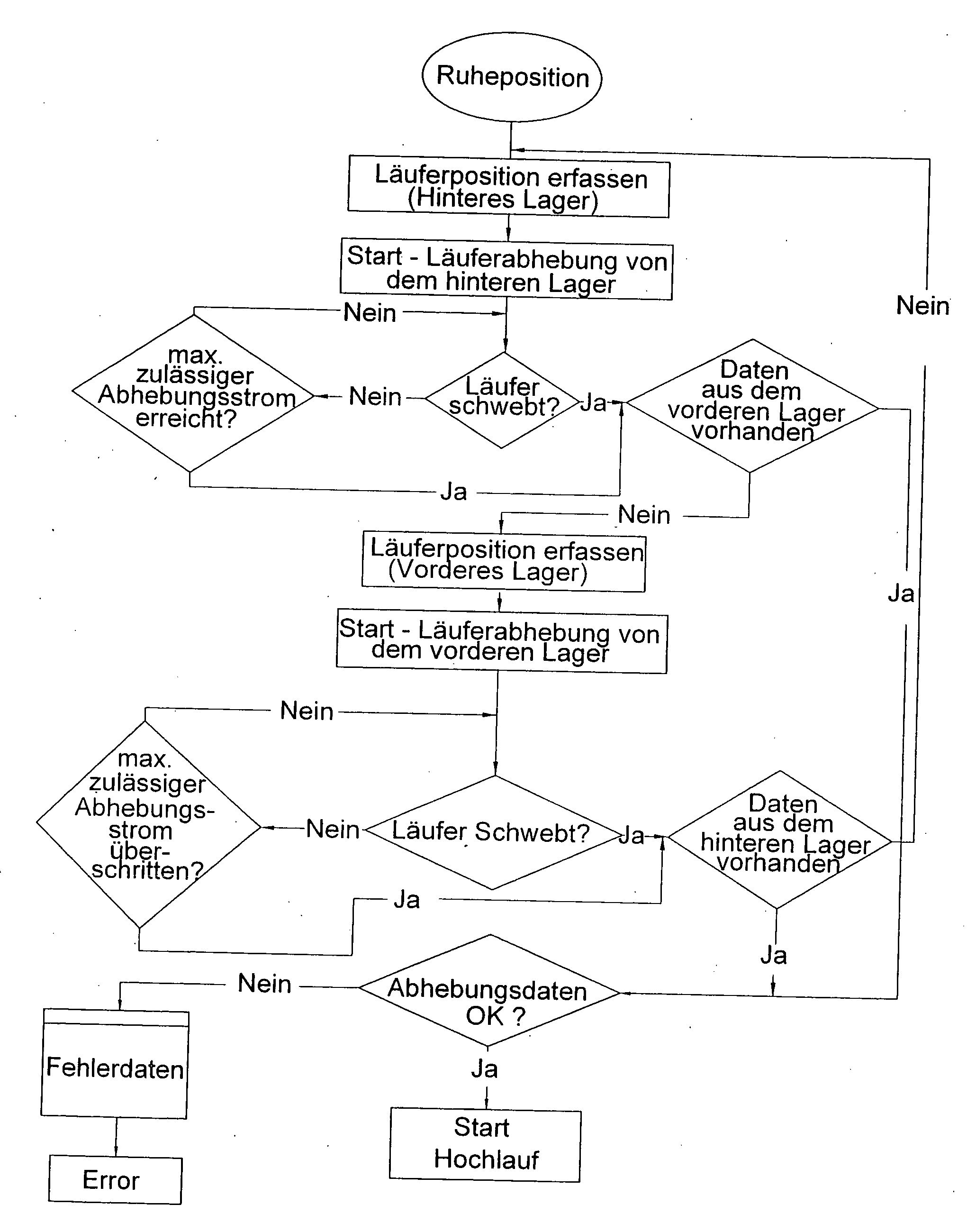
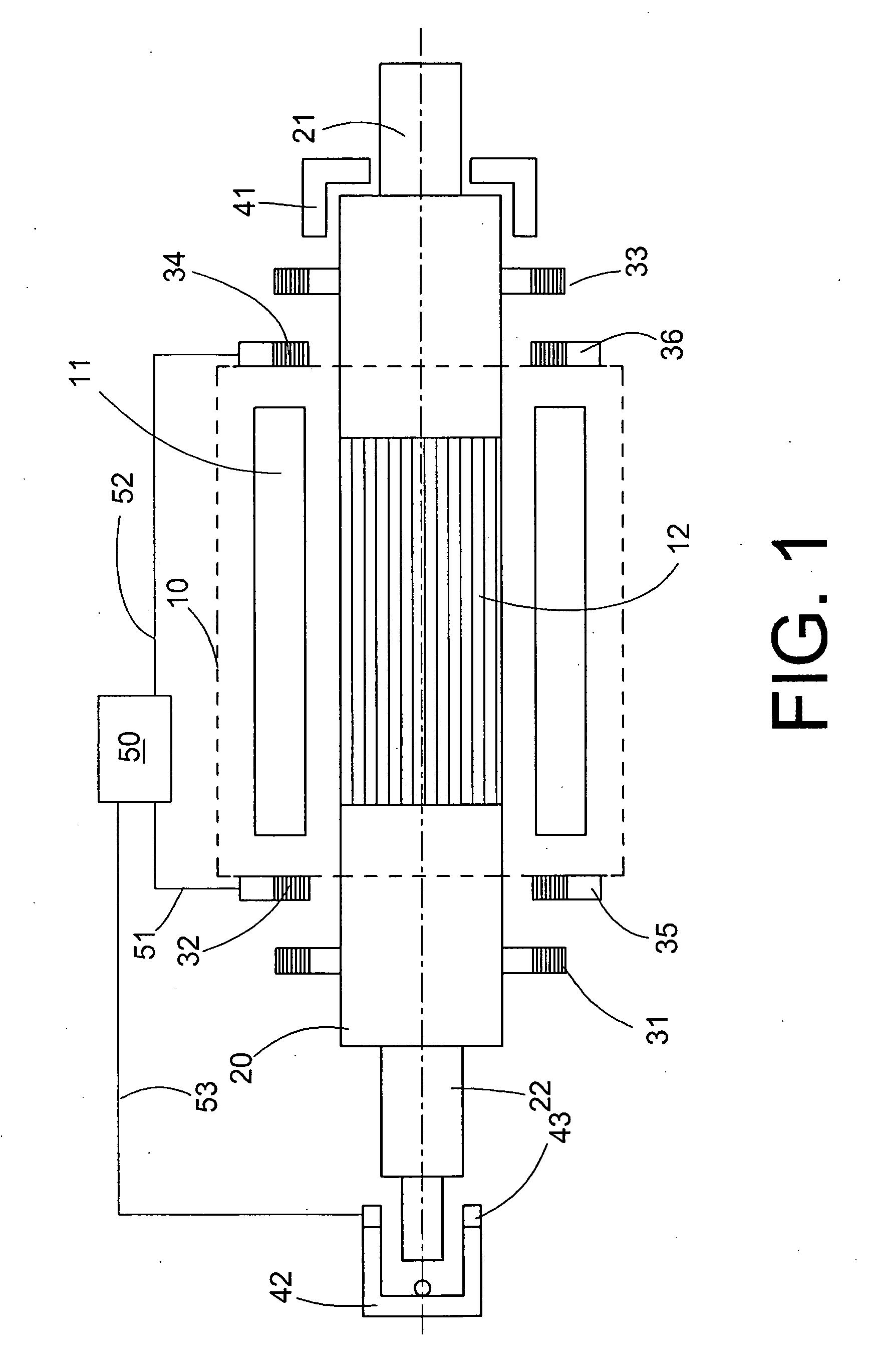
[0033]FIG. 1 shows a schematic view of an electric machine with a magnetically mounted rotor for rotating the spinning cup of an open-end spinning machine. In the embodiment shown, the electric machine 10 is an electronically commutated direct current motor. The motor 10 has, in the stator, a winding packet 11 and, in the rotor, a permanent magnet 12. The permanent magnet 12 is connected to the rotor 20. The rotor 20 has a front end 21 and a rear end 22. The front end 21 is mechanically coupled to a spinning cup, not shown here. A limitation bearing 41 is arranged at the front end and a limitation bearing 42 is arranged at the rear end. The limitation bearings offer protection in the event of failure or damage of the magnetic bearing, both in the axial and the radial direction. In addition, a position sensor 43 is located on the rear bearing to determine the position of the rotor 20 in the axial direction. An axially magnetised permanent magnetic ring is provided for the magnetic be...


PUM

PropertyMeasurementUnit
Forceaaaaaaaaaa
Currentaaaaaaaaaa

Abstract

A method and a device with a control apparatus (50) for starting an electric machine (10) with a rotor (20), particularly the spinning cup of an open-end spinning machine, magnetically mounted by a bearing having permanent magnets (31, 32, 33, 34). An actuator system controls the position in the axial direction (35, 36) and two limitation bearings (41, 42), determine the axial end positions of the rotor. The actuator system brings about a lifting from the first axial end position, and a system variable during such lifting is compared with a reference value, and the rotor (20) is moved into the second end position, and the actuator system brings about a lifting from the second axial end position, and a system variable on lifting from the second end position is compared with a reference value.

Description

CROSS REFERENCE TO RELATED APPLICATIONS[0001]This application claims the benefit of German patent application 10 2007 028 935.0, filed Jun. 22, 2007, herein incorporated by reference.BACKGROUND OF THE INVENTION[0002]The invention relates to a method and a device with a control apparatus for starting an electric machine with a magnetically mounted rotor, in particular for rotating the spinning cup of an open-end spinning machine. The magnetic bearing has permanent magnets, an actuator system for controlling the position in the axial direction and two axial limitation bearings, by means of which the axial end positions of the rotor are determined.[0003]Electric machines with magnetically mounted rotors are used, for example, as the drive of gas ultracentrifuges, turbomolecular pumps, tool spindles, compressors, blood pumps and flywheels. A magnetic bearing is advantageous in particular at high rotational speeds, as it has a significantly lower power loss compared to mechanical bearing...

Claims


Application Information

Patent Timeline
IPC IPC(8): H02P1/04
CPCF16C32/0442F16C32/0465F16C2231/00F16C32/0478D01H4/12F16C39/02F16C32/0446F16C2340/18F16C2380/26F16C32/0412H02P6/22D01H1/00H02P1/00
Inventor BALBOUL, NOUR-EDDINE
Owner SAURER SPINNING SOLUTIONS GMBH & CO KG
Why Eureka
Try Eureka