System and apparatus for electromagnetic noise detection in an mr imaging scanner environment

Inactive Publication Date: 2008-12-25
GENERAL ELECTRIC CO
View PDF5 Cites 51 Cited by
  • Summary
  • Abstract
  • Description
  • Claims
  • Application Information

AI Technical Summary

Problems solved by technology

During an MRI scan, electromagnetic noise or “spike noise” may be generated inside the scan room.
There may be multiple sources of spike noise in the scan room such as, for example, electrostatic discharge (ESD), voltage breakdown between conductors of a gradient coil of the MRI system, metal-on-metal vibration or contact, breaks or varying contact between electrical connections, etc.
Spike noise in the scan room that is detected by the receiver coils may lead to “white pixel” artifacts in an image or to possible damage to the imaging hardware.
A “w

Method used


Image

  • System and apparatus for electromagnetic noise detection in an mr imaging scanner environment
  • System and apparatus for electromagnetic noise detection in an mr imaging scanner environment
  • System and apparatus for electromagnetic noise detection in an mr imaging scanner environment

Examples


Embodiment Construction

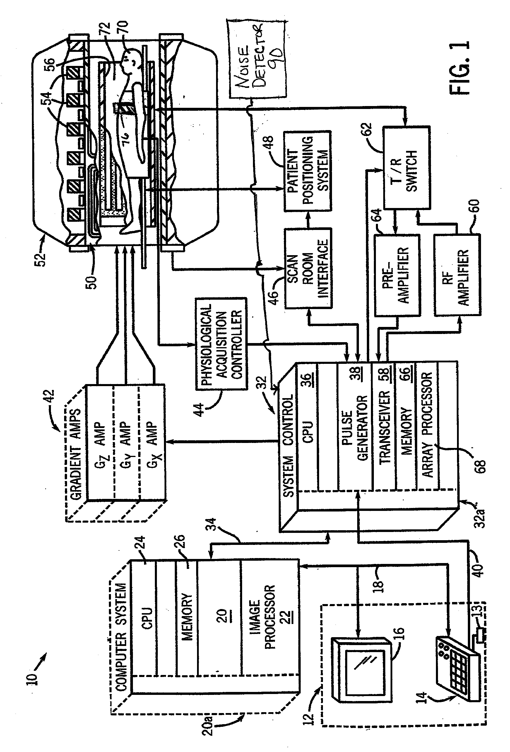
[0011]FIG. 1 is a schematic block diagram of an exemplary magnetic resonance imaging system in accordance with an embodiment. The operation of MRI system 10 is controlled from an operator console 12 that includes a keyboard or other input device 13, a control panel 14, and a display 16. The console 12 communicates through a link 18 with a computer system 20 and provides an interface for an operator to prescribe MRI scans, display the resultant images, perform image processing on the images, and archive data and images. The computer system 20 includes a number of modules that communicate with each other through electrical and / or data connections, for example such as are provided by using a backplane 20a. Data connections may be direct-wired links or may be fiber optic connections or wireless communication links or the like. These modules include an image processor module 22, a CPU module 24 and a memory module 26 which may include a frame buffer for storing image data arrays. In an a...


PUM


Abstract

A system for detecting electromagnetic noise in a magnetic resonance imaging (MRI) scanner environment includes an antenna configured to detect electromagnetic noise. The antenna includes a first conducting loop and a second conducting loop oriented perpendicularly to the first conducting loop. The system also includes a noise correction system coupled to the antenna and configured to receive noise signals from the antenna.

Description

FIELD OF THE INVENTION[0001]The present invention relates generally to magnetic resonance imaging (MRI) systems and in particular, to a system and apparatus for detecting electromagnetic noise in an MRI scanner environment.BACKGROUND OF THE INVENTION[0002]Magnetic resonance imaging (MRI) is a medical imaging modality that can create images of the inside of a human body without using x-rays or other ionizing radiation. MRI uses a powerful magnet to create a strong, uniform, static magnetic field (i.e., the “main magnetic field”). When a human body, or a part of a human body, is placed in the main magnetic field, the nuclear spins that are associated with the hydrogen nuclei in tissue water become polarized. This means that the magnetic moments that are associated with these spins become preferentially aligned along the direction of the main magnetic field, resulting in a small net tissue magnetization along that axis (the “z axis,” by convention). An MRI system also comprises compone...

Claims


Application Information

Patent Timeline
IPC IPC(8): G01R33/28
CPCA61B5/055
Inventor SAHA, SAIKAT
Owner GENERAL ELECTRIC CO
Why Eureka
Try Eureka