
Display driver

Inactive Publication Date: 2008-12-25
RENESAS ELECTRONICS CORP
View PDF1 Cites 21 Cited by
  • Summary
  • Abstract
  • Description
  • Claims
  • Application Information

AI Technical Summary

Benefits of technology

[0012]Hence, an object of the present invention is, in a function of power saving of a backlight which uses a pixel histogram of an image, to reduce power consumption of the backlight while maintaining high contrast sensitivity of a display image by making contrast high as well as reducing power consumption.
[0016]In conventional backlight control, darkening based on a reciprocal of an expansion rate (including an expansion amount) of the upper end side is performed. However, at this time, darkening is performed using a darkening amount (including a darkening rate) which is a value resulted from multiplying a reciprocal of an expansion rate by an adjustment amount (including an adjustment rate), and the darkening amount is suppressed to a value lower than the reciprocal of the expansion rate, thereby making the high contrast sensitivity high by an amount of the suppression of darkening. By making the adjustment amount large, the high contrast sensitivity of an image is emphasized, and by making the adjustment amount small, low power consumption of the backlight is emphasized.
[0018]Furthermore, by changing the adjustment amount in response to the expansion rate on the lower-gradation side, when the expansion rate is low, an image with relatively low contrast is presumed, and therefore, the adjustment amount is made large, that is, the darkening amount of the backlight is made small to brighten the image. When the expansion rate is high, an image with relatively high contrast is presumed, and therefore, the adjustment amount is made small, that is, the darkening amount of the backlight is made large (or leave it as it is) to keep the image as it is, so that the power consumption is reduced by the darkening amount.
[0020]According to the present invention, by the above-described first display driver, power consumption of the backlight can be reduced while remaining the high contrast sensitivity, which allows selection between an emphasis on the high contrast sensitivity and an emphasis on reduction in power consumption of the backlight depending on the adjustment amount.
[0021]Further, by the above-described second display driver, the adjustment amount is automatically adjusted. That is, a relatively dark image is brightened to increase the high contrast sensitivity, and it is presumed that a relatively bright image has the contrast sensitivity, so that power consumption of the backlight can be reduced.
[0022]Furthermore, by the third display driver, the adjustment amount is automatically adjusted. That is, when an image has relatively low contrast, the image is brightened to increase the high contrast sensitivity. When the image has relatively high contrast, the contrast sensitivity is presumed to be sufficient, so that power consumption of the backlight can be reduced.

Problems solved by technology

Because of this, there are problems that contrast of an output image is lowered when power of the backlight is reduced by using the technology disclosed in Japanese Patent Application Laid-Open Publication No. 11-65531 and obtaining high contrast sensitivity by using the technology disclosed in U.S. Pre-Grant Publication No. 2006 / 0050084 (Japanese Patent Application Laid-Open Publication No. 2006-73009) becomes difficult.

Method used


Image

  • Display driver
  • Display driver
  • Display driver

Examples


first embodiment

[0037]Hereinafter, a driver for a liquid crystal display device of a first embodiment of the present invention will be explained with reference to FIG. 1 to 4.

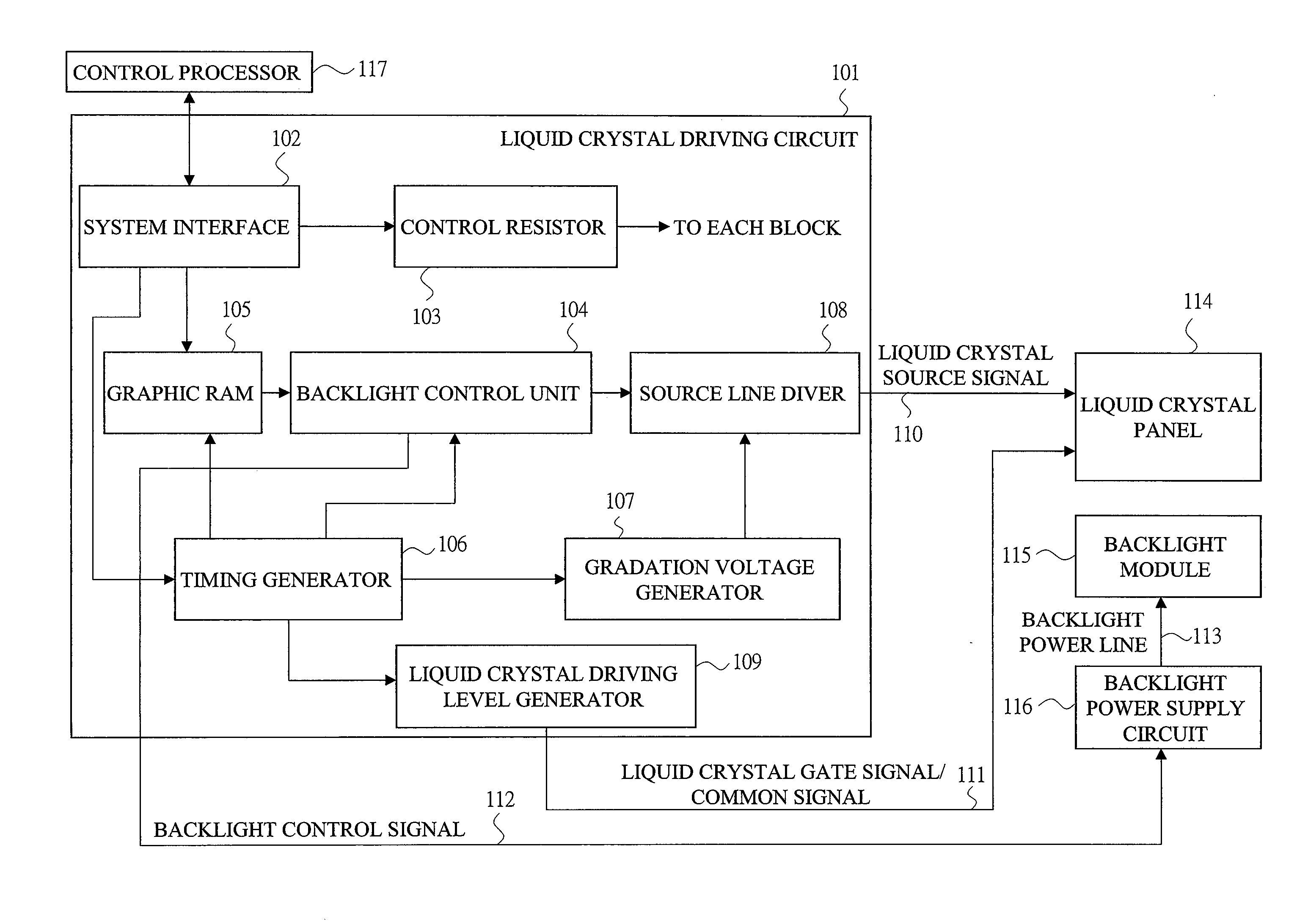
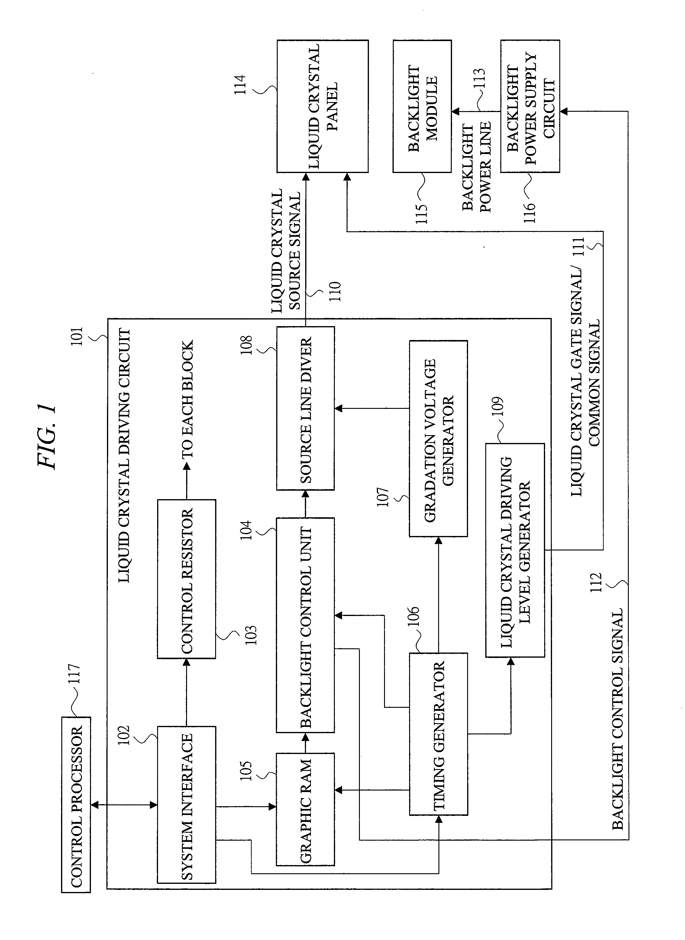
[0038]FIG. 1 is a drawing representing a configuration of the liquid crystal display device including the liquid crystal driver of the present embodiment. The liquid crystal display device includes a liquid crystal driver 101, a liquid crystal panel 114, a backlight module 115, a backlight power supply circuit 116, and a control processor 117.

[0039]The control processor 117 creates display data of an image and outputs it to the liquid crystal driver 101. The backlight power supply circuit 116 generates a desired voltage based on information of a backlight control signal 112 outputted from the liquid crystal driver 101 and supplies the voltage to a backlight power line 113. The liquid crystal panel 114 is inputted with a liquid crystal source signal 110 and a liquid crystal gate signal / common signal 111 from the liquid crystal ...

second embodiment

[0064]Hereinafter, a driver for a liquid crystal display device of a second embodiment of the present invention will be explained with reference to FIG. 5. The configuration of the liquid crystal display device including the liquid crystal driver of the present embodiment is similar to that of FIG. 1 of the first embodiment described above.

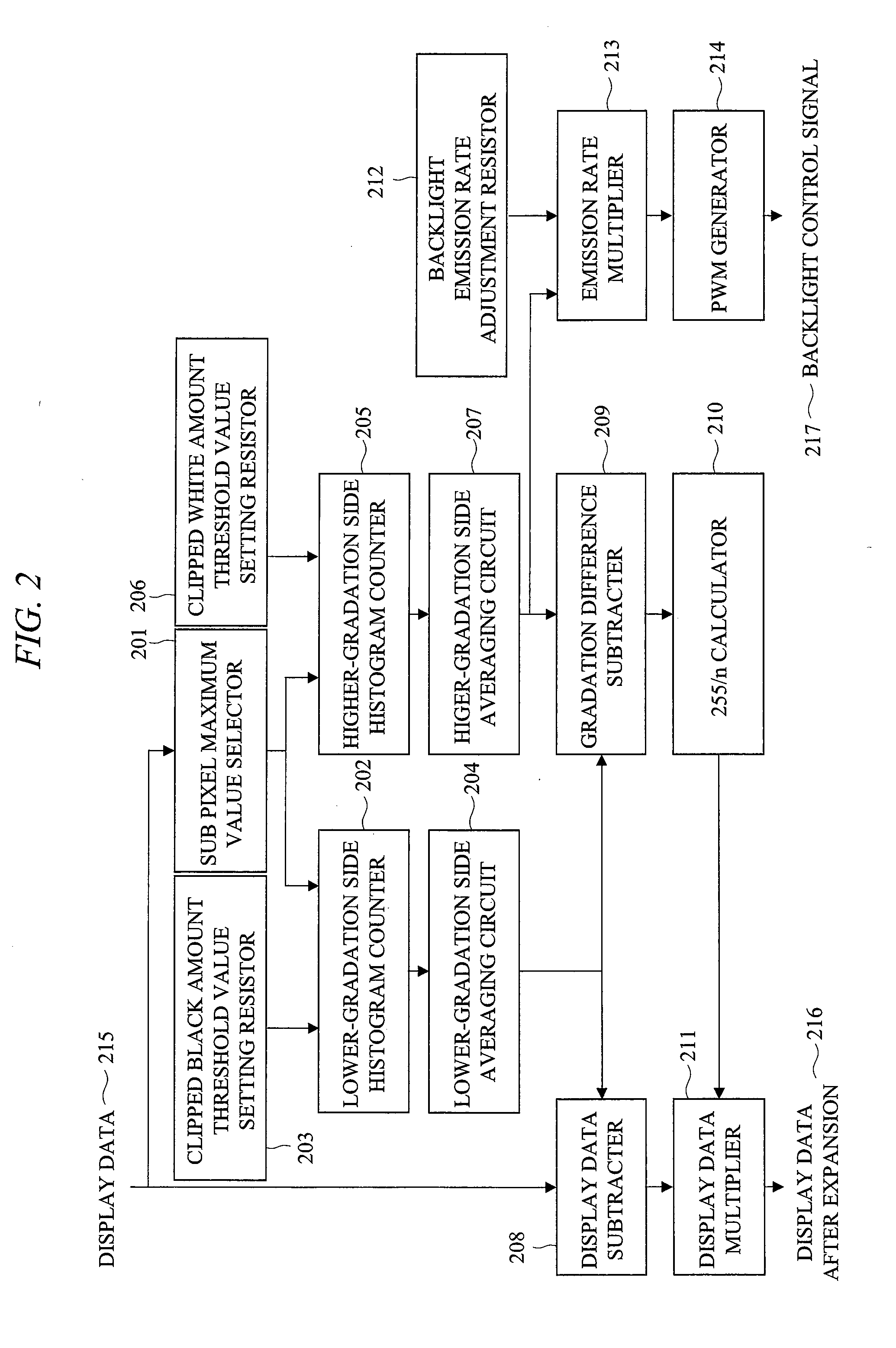
[0065]FIG. 5 is a drawing representing a detailed inner configuration of the backlight control unit 104 according to the present embodiment. In the configuration of FIG. 5, a backlight correction amount adjustment resistor 501 and a correction amount multiplier 502 are newly added in place of the backlight emission rate adjustment resistor 212 in the configuration of FIG. 2 of the first embodiment. The other components from the sub pixel maximum value selector 201 to the backlight control signal 217 are the same as those of the function block explained in FIG. 2 of the first embodiment, and therefore, the explanation thereof is omitted.

[0066]The c...

third embodiment

[0070]Hereinafter, a driver for a liquid crystal display device of a third embodiment of the present invention will be explained with reference to FIG. 6. The configuration of the liquid crystal display device including the liquid crystal driver of the present embodiment is similar to that of FIG. 1 of the first embodiment.

[0071]FIG. 6 is a drawing representing a detailed inner configuration of the backlight control unit 104 according to the present embodiment. In the configuration of FIG. 6, a lower-gradation side upper limit value resistor 601, an upper limit value difference subtracter 602, a backlight correction amount adjustment resistor 603, a lower-gradation side correction multiplier 604, and a correction amount multiplier 605 are newly added in place of the backlight emission rate adjustment resistor 212 and the emission rate multiplier 213 in the configuration of FIG. 2 of the first embodiment. The other components from the sub pixel maximum value selector 201 to the backl...


PUM


Abstract

A display driver driving a display panel according to inputted display data comprises: a first circuit changing brightness of a display image by conversion of the display data based on a first reference value and a second reference value, the first reference value being a display data value at a first position in an upper part of a histogram of the inputted display data, and the second reference value being a display data value at a second position in a lower portion of the histogram; a second circuit changing brightness of a illuminating device illuminating the display panel based on the first reference value; and a control circuit performing a processing of making the brightness of the display image high by the first circuit and a processing of making the brightness of the illuminating device low by the second circuit in correlation with the brightness of the display image.

Description

CROSS-REFERENCE TO RELATED APPLICATION[0001]The present application claims priority from Japanese application serial No. 2007-160910 filed on Jun. 19, 2007, the content of which is hereby incorporated by reference into this application.TECHNICAL FIELD OF THE INVENTION[0002]The present invention relates to a technology effective in applying to backlight control of a display device such as a liquid crystal display device, in particular, to backlight control capable of reducing power consumption while maintaining high contrast sensitivity.BACKGROUND OF THE INVENTION[0003]In recent years, a liquid crystal display is mounted on battery-powered information instruments and cellular phones. These liquid crystal displays are mostly a transmission type and a semi-transmission type which needs a backlight. Now, most of power consumption of a liquid crystal display portion is consumed by the backlight, and therefore, an idea for reduction in the power consumption has been desired. Particularly ...

Claims


Application Information

Patent Timeline
IPC IPC(8): G09G3/36
CPCG09G3/3406G09G3/3611G09G2320/064G09G2320/0646G09G2320/066G09G2330/021G09G2360/16G02F1/133G09G3/20G09G3/36G09G5/06
Inventor KUROKAWA, YOSHIKIKATAYAMA, YUKARIKUDO, YASUYUKIAKAI, AKIHITOTOSHIMA, GOKIAOYAMA, AKIHISA
Owner RENESAS ELECTRONICS CORP
Learn More