Electronic casing and method of manufacturing the same

Active Publication Date: 2008-12-25
METAL INDS RES & DEV CENT
View PDF3 Cites 8 Cited by
  • Summary
  • Abstract
  • Description
  • Claims
  • Application Information

AI Technical Summary

Benefits of technology

[0011]The present invention is mainly directed to a manufacturing method of an electronic casing which uses a metal laminate for casing material that has surface quality of titanium-based materials or stainless steel and is not exp

Problems solved by technology
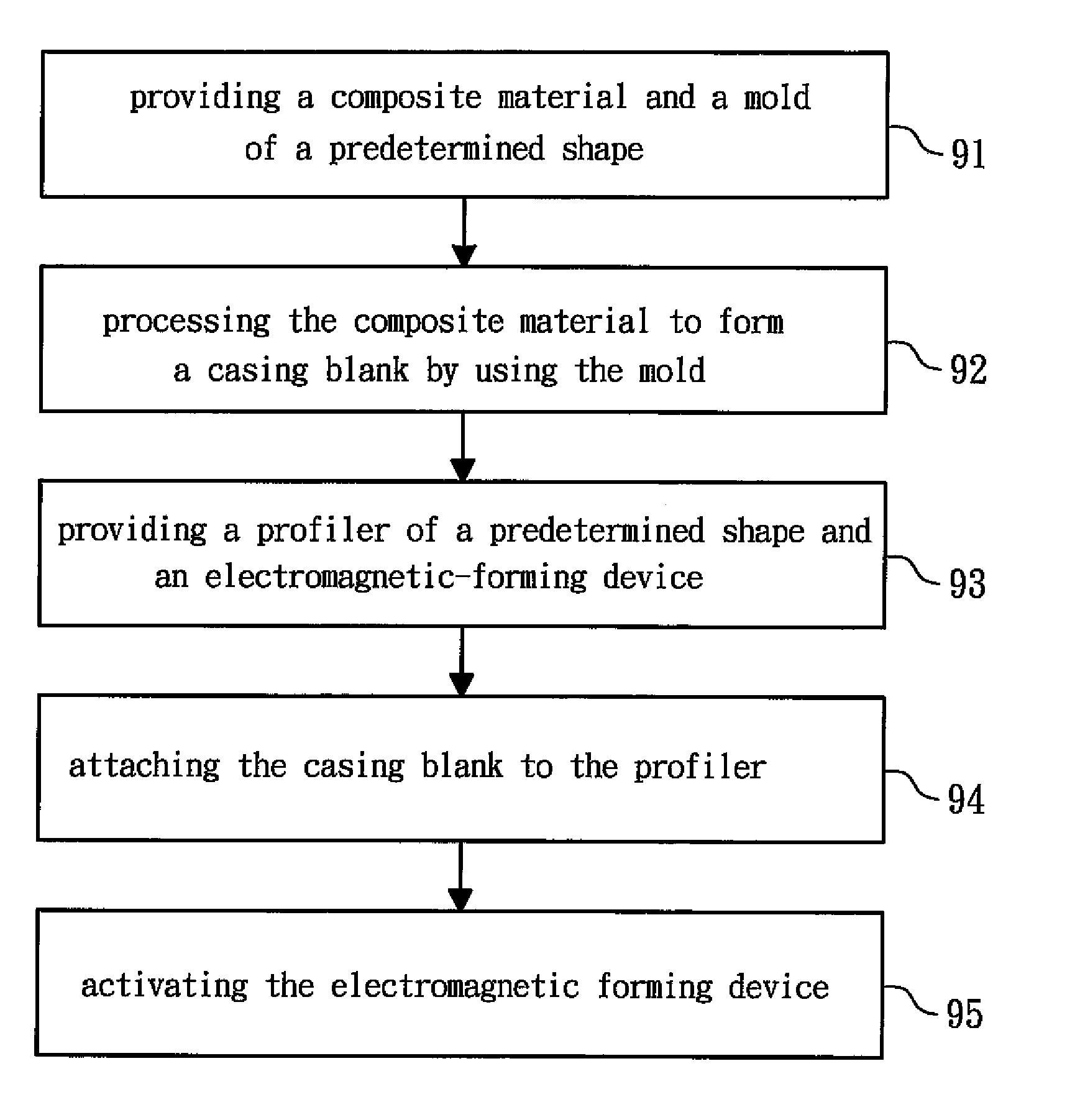
However, plastic casings made of polymer are not as good as the metal products in terms of appearance and strength.
Since plastic casings are neither shock-resistant nor abrasion-resistant, after being used for a long time, the casings of the products will suffer damage from shocks or abrasions, and the structural strength of the casings will also be weak.
Though metal materials are plated on the plastic casing through sputtering or electroplating to improve the appearance of the casing, the strength of the casing is not improved significantly.
However, the added value of aluminum-based material is rather low.
However, titanium-based material has a strong springback after the common stamping process, such it is difficult

Method used


Image

  • Electronic casing and method of manufacturing the same
  • Electronic casing and method of manufacturing the same
  • Electronic casing and method of manufacturing the same

Examples


Embodiment Construction

[0025]A preferred embodiment of the method of manufacturing an electronic casing according to the present invention is described below. In order to make the illustration be more comprehensible, the same reference numbers will be used throughout the drawings to refer to the same or similar parts.

[0026]FIG. 3 is a schematic view of a method of manufacturing a metal laminate to form an electronic casing according to the present invention. FIG. 4 is a cross-sectional view of the structure of FIG. 3 taken along a sectional line A-A′. As shown in FIG. 3, a metal laminate 3 at least includes a metal top layer 31 and a metal bottom layer 32. The metal top layer 31 can be made of a titanium-based material (i.e., titanium or titanium alloy) or stainless, and can be certainly made of other metals. The metal bottom layer 32 can be made of an aluminum-based material (i.e., aluminum or aluminum alloy). The metal top layer 31 and the metal bottom layer 32 pass through a pair of rollers 33, and the...


PUM

PropertyMeasurementUnit
Thicknessaaaaaaaaaa
Shapeaaaaaaaaaa

Abstract

An electronic casing and a method of manufacturing the same are provided. The method includes the following steps. Step (a): a metal laminate and a die of a predetermined shape are provided. The metal laminate comprises a metal top layer and a metal bottom layer that are bonded by interface atom diffusion. Step (b): the metal laminate is processed to form a casing blank by using the die, and the casing blank has at least one turning portion. Step (c): a profiler of a predetermined shape and an electromagnetic forming device are provided. Step (d): the casing blank is attached to the profiler, and the electromagnetic forming device is disposed at a position corresponding to the turning portion. Step (e): the electromagnetic forming device is activated, so that the casing blank has a shape corresponding to the predetermined shape of the profiler.

Description

BACKGROUND OF THE INVENTION[0001]1. Field of the Invention[0002]The present invention relates to an electronic casing and a method of manufacturing the same. More particularly, the present invention relates to a method of manufacturing an electronic casing that enables the electronic casing to have desirable surface quality and an electronic casing manufactured thereby.[0003]2. Description of the Related Art[0004]With the rapid progress of our times and the rapid development of electronic products, more and more people carry with one or more portable electronic product, such as cell phone, PDA, or walkman. In the prior art, in order to improve the portability, the electronic products are developed to become lighter, thinner and smaller. Moreover, in order to reduce the weight, casings of the electronic products are often made of plastic such as polymer with a light weight.[0005]However, plastic casings made of polymer are not as good as the metal products in terms of appearance and ...

Claims


Application Information

Patent Timeline
IPC IPC(8): H05K5/04B32B15/01B21D26/00
CPCB21D26/14B21D51/54B32B15/012B32B15/017Y10S72/707Y10T428/12736Y10T29/49885Y10T29/49073H05K5/04
Inventor CHEN, CHIH-YUANWANG, CHUN-CHIEHSUE, TZYY-KERHUANG, CHIN-CHUANCHUNG, CHI-KEUNG
Owner METAL INDS RES & DEV CENT
Why Eureka
Try Eureka