Buck converter LED driver circuit

a technology of led driver circuit and led converter, which is applied in the direction of electric variable regulation, process and machine control, instruments, etc., can solve the problems of large change in operating current, surge current above rated current value tending to degrade or even damage the led, and narrow range of conducting phase angle, etc., to achieve simple design and high input power factor

Inactive Publication Date: 2008-12-25
GREEN MARK TECH
View PDF4 Cites 136 Cited by
  • Summary
  • Abstract
  • Description
  • Claims
  • Application Information

AI Technical Summary

Benefits of technology

[0008]Accordingly, the present invention is directed to a buck converter LED driver circuit. The driver circuit features a simple design and a high input power factor without the requirement for a large capacitor.

Problems solved by technology

At its operating range, a slight change of forward voltage results in a large change in its operating current.
Any surge current above its rated current value will tend to degrade or even damage the LED.
The large capacitance of Cin leads to a narrow range of conducting phase angle and a very poor input power factor.
Although the driver circuit in FIG. 3 has a higher power factor, it is far more complex than the driver circuit in FIG. 1.
In many LED lamp fixtures, there is not sufficient space for the additional components.

Method used


Image

  • Buck converter LED driver circuit
  • Buck converter LED driver circuit
  • Buck converter LED driver circuit

Examples


Embodiment Construction

[0020]Reference will now be made in detail to the present embodiments of the invention, examples of which are illustrated in the accompanying drawings. Wherever possible, the same reference numbers are used in the drawings and the description to refer to the same or like parts.

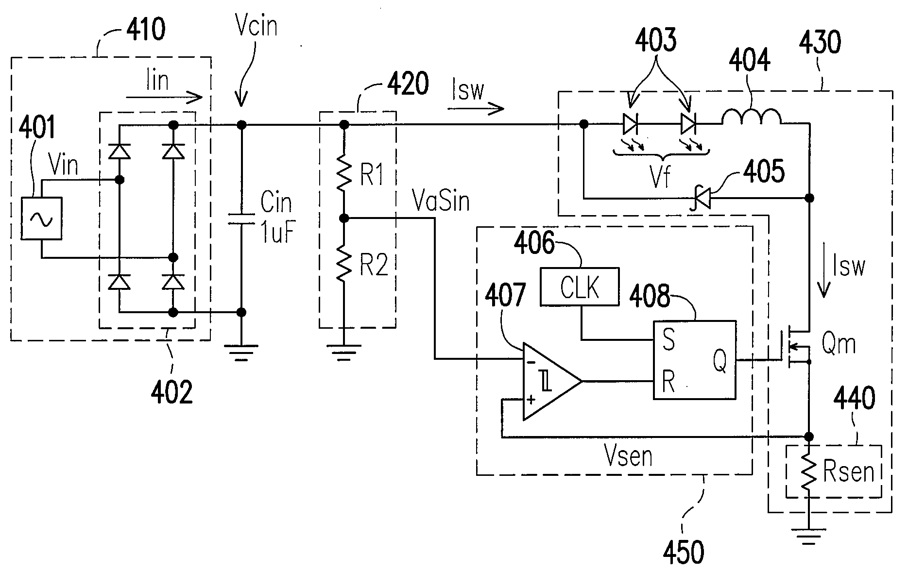
[0021]Please refer to FIG. 4. FIG. 4 is a schematic diagram showing a buck converter LED driver circuit according to an embodiment of the present invention. This driver circuit includes a rectified AC voltage source 410, a capacitor Cin, a voltage waveform sampler 420, a buck power stage 430, and a control circuit 450. The buck power stage 430 includes two LEDs 403 and provides a voltage signal Vsen which is directly proportional to the current through LEDs 403. The rectified AC voltage source 410 is coupled to buck power stage 430 for driving buck power stage 430. The capacitor Cin is coupled between the two output ends of the rectified AC voltage source 410. Voltage waveform sampler 420 is coupled to the rec...


PUM


Abstract

A buck converter LED driver circuit is provided. The driver circuit includes a buck power stage, a rectified AC voltage source, a voltage waveform sampler, and a control circuit. The buck power stage includes at least one LED and provides a first signal directly proportional to the current through the LED. The rectified AC voltage source is coupled to the buck power stage for driving the buck power stage. The voltage waveform sampler is coupled to the rectified AC voltage source for providing a second signal directly proportional to the voltage provided by the rectified AC voltage source. The control circuit is coupled to the voltage waveform sampler and the buck power stage for turning on and turning off the buck power stage according to a comparison between the first signal and the second signal.

Description

BACKGROUND OF THE INVENTION[0001]1. Field of the Invention[0002]The present invention relates to a light-emitting diode (LED) driver circuit. More particularly, the present invention relates to a buck converter LED driver circuit.[0003]2. Description of the Related Art[0004]An LED is similar to a silicon p-n junction diode. At its operating range, a slight change of forward voltage results in a large change in its operating current. Therefore, an LED requires constant current drive, not constant voltage drive. Any surge current above its rated current value will tend to degrade or even damage the LED.[0005]Please refer to FIG. 1 and FIG. 2. FIG. 1 is a schematic diagram showing a conventional LED driver circuit with a buck converter topology. FIG. 2 shows some important waveforms in the LED driver circuit in FIG. 1. The alternating current (AC) voltage source 101 drives LEDs 103 through bridge rectifier 102. LEDs 103, inductor 104, and diode 105 are coupled as a loop. Here diode 105...

Claims


Application Information

Patent Timeline
Patent Type & Authority Applications(United States)
IPC IPC(8): H02M3/335
CPCH05B33/0815H05B45/375
Inventor LIU, KWANG-HWA
Owner GREEN MARK TECH
Why Eureka
Try Eureka