High forward current diodes for reverse write 3D cell

a reverse write, high-current technology, applied in the direction of diodes, digital storage, instruments, etc., can solve the problems of difficult fabrication and operation of three-terminal devices, complex solutions for achieving erasable or multi-state cells, and difficult work of chalcogenides

Active Publication Date: 2008-12-25
SANDISK TECH LLC
View PDF57 Cites 33 Cited by
  • Summary
  • Abstract
  • Description
  • Claims
  • Application Information

AI Technical Summary

Problems solved by technology

Some solutions for achieving erasable or multi-state cells are complex.
These memory cells are three-terminal devices which are relatively difficult to fabricate and operate at the ver...

Method used


Image

  • High forward current diodes for reverse write 3D cell
  • High forward current diodes for reverse write 3D cell
  • High forward current diodes for reverse write 3D cell

Examples


example

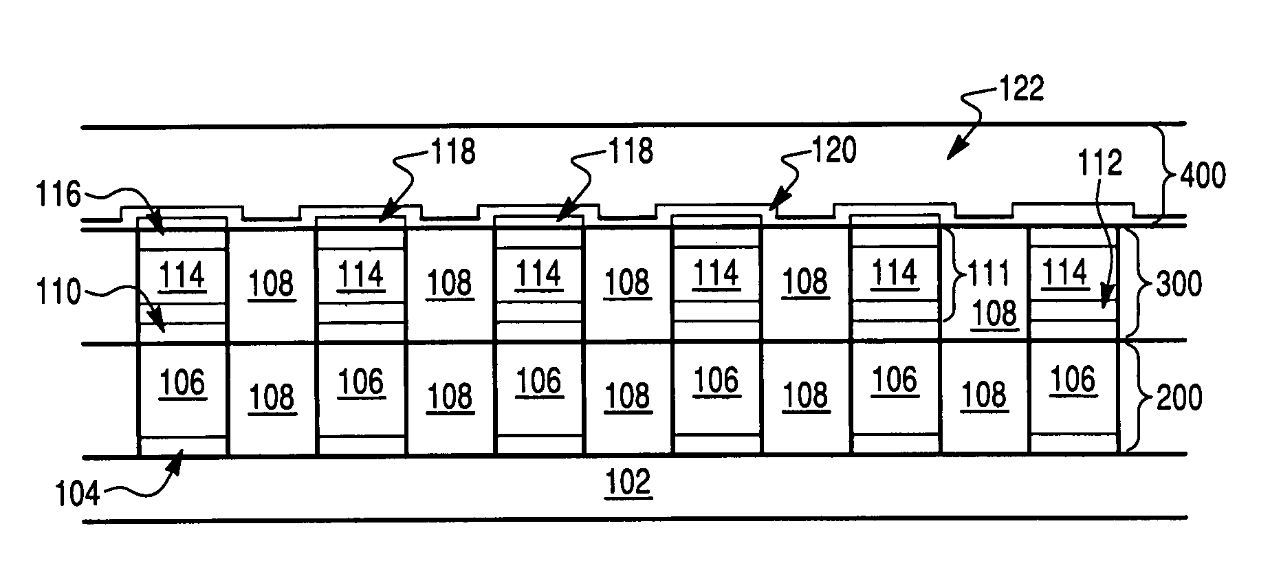
[0092]Fabrication of a single memory level will be described in detail. Additional memory levels can be stacked, each monolithically formed above the one below it. In this embodiment, a polycrystalline semiconductor diode will serve as the switchable memory element.

[0093]Turning to FIG. 15a, formation of the memory begins with a substrate 100. This substrate 100 can be any semiconducting substrate as known in the art, such as monocrystalline silicon, IV-IV compounds like silicon-germanium or silicon-germanium-carbon, III-V compounds, II-VII compounds, epitaxial layers over such substrates, or any other semiconducting material. The substrate may include integrated circuits fabricated therein.

[0094]An insulating layer 102 is formed over substrate 100. The insulating layer 102 can be silicon oxide, silicon nitride, high-dielectric film, Si—C—O—H film, or any other suitable insulating material.

[0095]The first conductors 200 are formed over the substrate and insulator. An adhesion layer ...


PUM


Abstract

A nonvolatile memory device includes at least one memory cell which comprises a diode and a metal oxide antifuse dielectric layer, and a first electrode and a second electrode electrically contacting the at least one memory cell. In use, the diode acts as a read/write element of the memory cell by switching from a first resistivity state to a second resistivity state different from the first resistivity state in response to an applied bias.

Description

[0001]This application is related to Herner, U.S. application Ser. No. ______, titled “METHOD OF MAKING HIGH FORWARD CURRENT DIODES FOR REVERSE WRITE 3D CELL” (Attorney Docket No. 035905 / 0157), filed on the same day herewith, and hereby incorporated by reference in its entirety.BACKGROUND OF THE INVENTION[0002]The invention relates to a nonvolatile memory array.[0003]Nonvolatile memory arrays maintain their data even when power to the device is turned off. In one-time-programmable arrays, each memory cell is formed in an initial unprogrammed state, and can be converted to a programmed state. This change is permanent, and such cells are not erasable. In other types of memories, the memory cells are erasable, and can be rewritten many times.[0004]Cells may also vary in the number of data states each cell can achieve. A data state may be stored by altering some characteristic of the cell which can be detected, such as current flowing through the cell under a given applied voltage or th...

Claims


Application Information

Patent Timeline
IPC IPC(8): G11C11/36
CPCG11C11/5692G11C13/003G11C13/0069G11C17/16G11C17/165G11C2013/009G11C2213/33G11C2213/71G11C2213/72H01L27/101H01L27/1021
Inventor HERNER, S. BRAD
Owner SANDISK TECH LLC
Why Eureka
Try Eureka