Base Station System

a base station and system technology, applied in the field of base station systems, can solve the problems of increasing the network operation cost, adding mounting and cost, and difficulty in mounting the rf cable, so as to improve the covering ability of the base station and reduce the network operation cost

Active Publication Date: 2008-12-25
DATANG MOBILE COMM EQUIP CO LTD
View PDF3 Cites 31 Cited by
  • Summary
  • Abstract
  • Description
  • Claims
  • Application Information

AI Technical Summary

Benefits of technology

[0012]A main objective of the present invention is to provide a base station system, which can improve a covering ability of the base station and can reduce a network operation cost.

Problems solved by technology

In addition, since the area covered by the base station is decided by the RF transceiver module while the RF transceiver module of the conventional base station belongs to the indoor part, when the wireless communication needs to cover larger and larger area, there should be many base station sites so as to cover different areas with the conventional base stations, therefore, the network operation cost increases.
In addition, since the design of the conventional base station makes the indoor part and the outdoor part of the base station transmitting signals through the RF cable and the RF cable is thick and heavy, which brings difficulty in mounting the RF cable.
Especially, if the base station adopts the smart antenna, multiple RF cables should be mounted, which adds difficulty in mounting and cost.

Method used


Image

  • Base Station System
  • Base Station System
  • Base Station System

Examples


embodiment 1

Digital Baseband Remote Manner

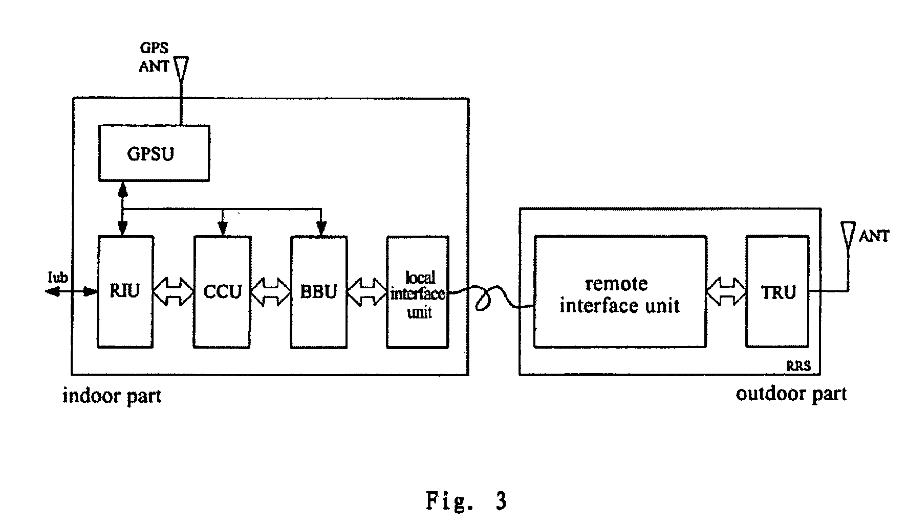
[0079]FIG. 4 is a schematic diagram showing a configuration of a base station system according to a first embodiment of the present invention.

[0080]The local interface unit is a local baseband interface unit (BIU-L). The functions of the local interface unit are: (1) through the downlink path of the local interface unit, the BIU-L receives the digital baseband signal from the BBU, converts the electric signal to a digital baseband optical signal and transmits the optical signal to the remote interface unit, wherein the interface signal is the digital baseband optical signal; (2) through the uplink path of the local interface unit, the BIU-L receives the interface signal, i.e. a digital baseband optical signal from the remote interface unit, converts the optical signal to a digital baseband electric signal and transmits the electric signal to the BBU. The BIU-L may implement its functions by an optical transceiver module with an electric / optical conversi...

embodiment 2

IF Remote Manner

[0086]FIG. 6 is a schematic diagram showing a configuration of a base station system according to a second embodiment of the present invention.

[0087]The local interface unit includes an IFU and an IIU-L. The IFU is a digital IF module of the conventional RFU. The configuration of the IIU-L includes two parts, i.e., a downlink path and an uplink path, as shown in FIG. 7(a) and FIG. 7(b) respectively.

[0088]FIG. 7(a) is a schematic diagram showing modules constituting the downlink path of the local IF interface unit and their functions. As shown in FIG. 7(a), the IIU-L downlink path includes the following modules.

[0089]If the IIU-L is connected with an remote IF interface unit (IIU-R) of the RRS through an IF cable, the IIU-L includes first up-conversion modules, a frequency shift keying (FSK) modulating module and a first multiplexing module; if the IIU-L is connected with the IIU-R of the RRS through an optical cable, the IIU-L includes first up-conversion modules, a ...

embodiment 3

Digital Baseband Remote Manner Plus IF Remote Manner

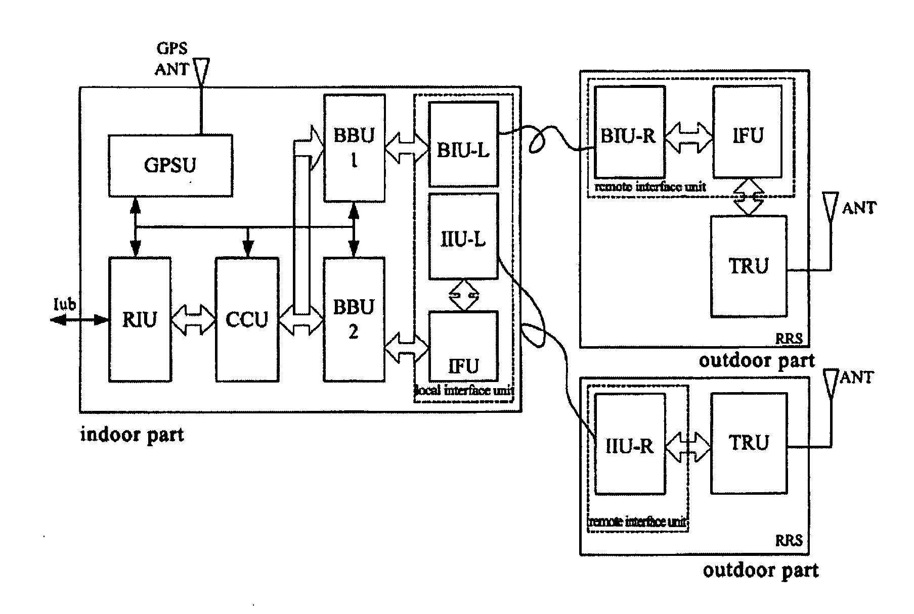
[0117]FIG. 9 is a schematic diagram showing a configuration of a base station system according to the third embodiment of the present invention.

[0118]The local interface unit includes three units that are the BIU-L, IFU and IIU-L and the two remote interface units includes three units that are the BIU-R, IFU and IIU-R respectively.

[0119]The indoor part further includes the RIU, CCU, BBU1, BBU2 and GPSU. It should be noted here that in the current embodiment, the BIU-L and the IFU of the indoor part may correspond to one BBU respectively, as shown in FIG. 9, i.e. the configuration and function of BBU1 and BBU2 are the same, and may also share one BBU. The RRS further includes the TRU.

[0120]The structure of the current embodiment shows in practice, this kind of base station system may be more flexible. One base station structure can support two remote manners so that the user may flexibly choose the remote manner according to the dis...


PUM


Abstract

The present invention discloses a base station system, including an indoor part and a remote RF subsystem (RRS). The indoor part includes a RIU, a CCU, a BBU, a GPSU and a local interface unit. The RRS includes a remote interface unit, a RF transceiver unit (TRU) and an antenna. The local interface unit and the remote interface unit are for signal intercommunicating between the indoor part of the base station and the RSS. The TRU is a RF transceiver module of the conventional RFU, for amplifying an analog RF signal from the remote interface unit and transmitting the signal to the antenna. By flexibly selecting between an optical cable and an If cable, the interface unit of the present invention provides a digital baseband remote manner and an IF remote manner. According to the structure of the base station of the present invention, the number of the base station sites and the network operating cost decreases; on the other side, since one base station may cover a cell by smart antenna with only one optical cable or IF cable, the difficulty in mounting is reduced.

Description

FIELD OF THE INVENTION[0001]The present invention relates to a design of base station architecture, especially to a base station system.BACKGROUND OF THE INVENTION[0002]In a wireless cellular communication system, a wireless access network includes two main parts which are a base station system and a wireless network controller respectively, wherein the design of the base station system directly influences the networking mode of the wireless network, the covering quality of the network and the operation cost of constructing the network.[0003]The importance of the design of the base station system will be analyzed with an example of the TD-SCDMA system.[0004]FIG. 1 is a schematic diagram showing a configuration of a conventional base station. As shown in FIG. 1, in the TD-SCDMA system, Node B is connected with a radio network controller (RNC) through a standard Iub interface and Node B includes two parts which are located indoors and outdoors respectively.[0005]The outdoor part of No...

Claims


Application Information

Patent Timeline
Patent Type & Authority Applications(United States)
IPC IPC(8): H04J14/00H04B1/38H04B1/3822H04B1/40H04W88/08
CPCH04W88/08H04W88/085
Inventor LI, SHIHEXU, TIEZHUWANG, HONGBOWANG, LIWEICHEN, XIAOZHOULIU, XIANZHAO, GUOXINWU, JIANFENG
Owner DATANG MOBILE COMM EQUIP CO LTD
Why Eureka
Try Eureka