DC-DC Converter

a converter and dc technology, applied in the direction of electric variable regulation, process and machine control, instruments, etc., can solve the problems of difficult to properly design the dc-dc converter, and generally impossible or very difficult to obtain such output voltage directly from the voltage source, etc., to reduce noise, not complicated and expensive

Active Publication Date: 2009-01-01
NEC TOSHIBA SPACE SYST
View PDF4 Cites 21 Cited by
  • Summary
  • Abstract
  • Description
  • Claims
  • Application Information

AI Technical Summary

Benefits of technology

[0021]The DC-DC converter according to the present invention exhibits the following practical advantages. That is, it is possible to provide the non-isolated DC-DC converter having the output voltage of any desired value and the same polarity (or non-inverted) by stepping-up / down the voltage of the input voltage source while reducing the noise. Accordingly, the DC-DC converter according to the present invention is most suitable to those applications to provide a stabilized output voltage to be supplied to the load from solar panels installed on planet explores or the like. Moreover, the DC-DC converter according to the present invention is not complicated and expensive as compared to conventional DC-DC converters because the required circuit elements are coils, capacitors, a switching device and a diode.

Problems solved by technology

It is generally impossible or very difficult to obtain such output voltage directly from a voltage source such as a battery or the like.
If the voltage from the solar panels fluctuates over a wide range, the maximum or peak output voltage from the solar panels tends to be very high, it is difficult to properly design the DC-DC converter.
If the voltage from the solar panels fluctuates largely, it is also difficult to properly design the DC-DC converter in this case because the output voltage from the solar panels could become very low.
However, a non-isolated stepping-up / down DC-DC converter with low power consumption has such a problem that the input and output voltages are in opposite polarity to each other and thus difficult to handle.
All of these DC-DC converters have common problems that the input and output voltages are opposite polarity to each other and the input and output currents are pulse waves, thereby exhibiting large noise.
This means that the pulsating input and output currents have large amplitudes at the switching frequency and a large rate of change in time, thereby providing a large noise at the switching frequency as well as large harmonic noises at the frequencies equal to the switching frequency multiplied by any integer.
As described hereinabove, the conventional DC-DC converters as shown in FIGS. 12-16 are difficult to handle because of opposite polarity between the input and output voltages or difficult to be applied to such applications critical to noise because they are subjected to a large noise due to ripples in the input and output currents.

Method used


Image

  • DC-DC Converter
  • DC-DC Converter
  • DC-DC Converter

Examples


first embodiment

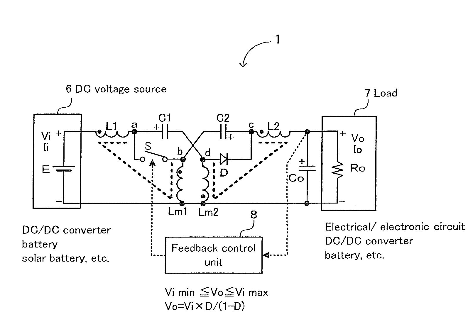
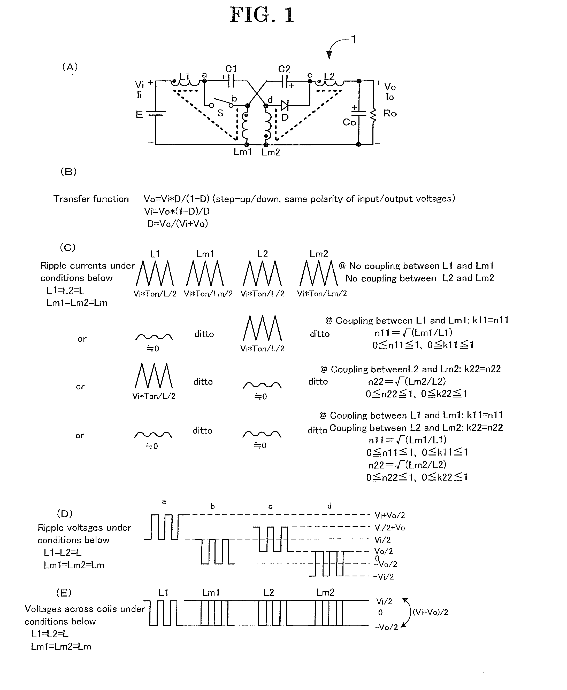
[0040]Firstly, a reference is made to FIG. 1 illustrating a first embodiment of the DC-DC converter according to the present invention. In FIG. 1, (A) is the circuit schematic of the DC-DC converter according to the present invention, (B) is a transfer function, (C) is ripple currents, (D) is a ripple voltage and (E) is a coil voltage.

[0041]As shown in FIG. 1(A), the DC-DC converter 1 comprises an input voltage source E, an input coil (or an inductor) L1, an output coil L2, a first intermediate coil Lm1, a second intermediate coil Lm2, an input (or a first intermediate) capacitor C1, an output (or a second intermediate) capacitor C2, a switch S, a diode D and a parallel connection of a load resistor Ro and an output (or a smoothing) capacitor Co.

[0042]The input coil L1, the input capacitor C1 and the second intermediate coil Lm2 are connected in series between the both terminals of the input voltage source E. Connected in series between both ends of the parallel connection of the lo...

third embodiment

[0081]FIG. 10 is the circuit schematic of the DC-DC converter according to the present invention. This DC-DC converter 3 is an example of using power MOS FETs (MOS type field effect transistors) as the switch S and the diode D. Diodes that are connected in parallel with the power MOS FETs represent parasitic diodes of the power MOS FETs. The ON time of the switch S is controlled by the feedback control section 8 so that the output voltage will be a desired voltage. During the OFF period of the switch S, the power MOS FET that replaces the diode D is turned ON (synchronized rectification), thereby enabling to reduce power loss of the power MOS FET. Since the other circuit configurations remain unchanged, no duplicated operation will be given herein.

fourth embodiment

[0082]Now, FIG. 11 shows the circuit schematic of the DC-DC converter according to the present invention. The basic circuit configuration of this DC-DC converter 4 is the same as the DC-DC converter 3 as shown in FIG. 10. However, a close look at this DC-DC converter 4 proves a symmetrical configuration at the left and right sides, or the input-output sides. It has been described hereinabove that the DC-DC converter operates as the step-up / down converter with the left and right sides acting respectively as the input and output sides by controlling the ON time of the switch S. Because of the symmetrical configuration, it can be operated as a step-up / down converter with the right and left sides acting as the input and output sides when controlling the ON time of the power MOS FET used as a replacement of the diode D. In other words, this DC-DC converter 4 can also be operated as a bi-directional step-up / down converter. A DC power supply bus having the DC voltage source 6 at the left s...


PUM


Abstract

Disclosed is a low noise, non-isolated DC-DC converter for providing a non-inverted (i.e., the same polarity as an input voltage) output voltage of any desired voltage by stepping-up/down the input voltage. It comprises an input coil L1, an input capacitor C1 and a second intermediate coil Lm2 connected in series between both ends of the input voltage source, an output coil L2, an output capacitor C2 and a first intermediate coil Lm1 connected in series between both ends of a load Ro, a switching device S connected between a node a of the L1 and the C1 and a node b of the C2 and the Lm1, and a diode D connected between a node d of the C1 and the Lm2 and a node c of the C2 and the L2.

Description

INCORPORATION BY REFERENCE[0001]This application is based upon and claims the benefit of priority from Japanese patent application no. 2007-171688, filed on Jun. 29, 2007, the disclosure of which is incorporated herein in its entirety by reference.FIELD OF THE INVENTION[0002]The present invention relates to a DC-DC converter, more specifically to anon-isolated (or non-insulated) type switching DC-DC converter for stepping-up or stepping down a relatively fluctuating input power supply voltage of a solar panel or the like to a stabilized desired output voltage.BACKGROUND OF THE INVENTION[0003]A power supply for providing a desired output voltage is absolutely necessary in order to cause an electronic circuit or electronic circuitries for various electronic apparatus, applied electronic apparatus or the like to operate properly. It is generally impossible or very difficult to obtain such output voltage directly from a voltage source such as a battery or the like. Particularly, a power...

Claims


Application Information

Patent Timeline
Patent Type & Authority Applications(United States)
IPC IPC(8): G05F1/00
CPCH02M3/158H02M3/005Y10S323/906
Inventor YOSHIDA, TEIJI
Owner NEC TOSHIBA SPACE SYST
Why Eureka
Try Eureka