Image Processing Apparatus, Image Processing System, and Control Method Therefor

a technology of image data and image processing equipment, applied in the field of image data storage, can solve the problems of high storage capacity of storage devices, frequent redundant storage of image data, etc., and achieve the effect of maximizing the use of storage devices

Inactive Publication Date: 2009-01-01
CANON KK
View PDF4 Cites 19 Cited by
  • Summary
  • Abstract
  • Description
  • Claims
  • Application Information

AI Technical Summary

Benefits of technology

[0007]According to the present invention, if substantially identical image data are stored in the predetermined storage device for use in future security chasing, at least one of the image data is retained. Each of the remaining identical image data is replaced with link information whose data size is relatively small, and the link information is stored. Accordingly, it is possible to use the storage device more effectively than ever before.

Problems solved by technology

Also, identical image data are often redundantly stored in the storage device.
In this case, the storage capacity of the storage device is particularly likely to be wasted.

Method used


Image

  • Image Processing Apparatus, Image Processing System, and Control Method Therefor
  • Image Processing Apparatus, Image Processing System, and Control Method Therefor
  • Image Processing Apparatus, Image Processing System, and Control Method Therefor

Examples


first embodiment

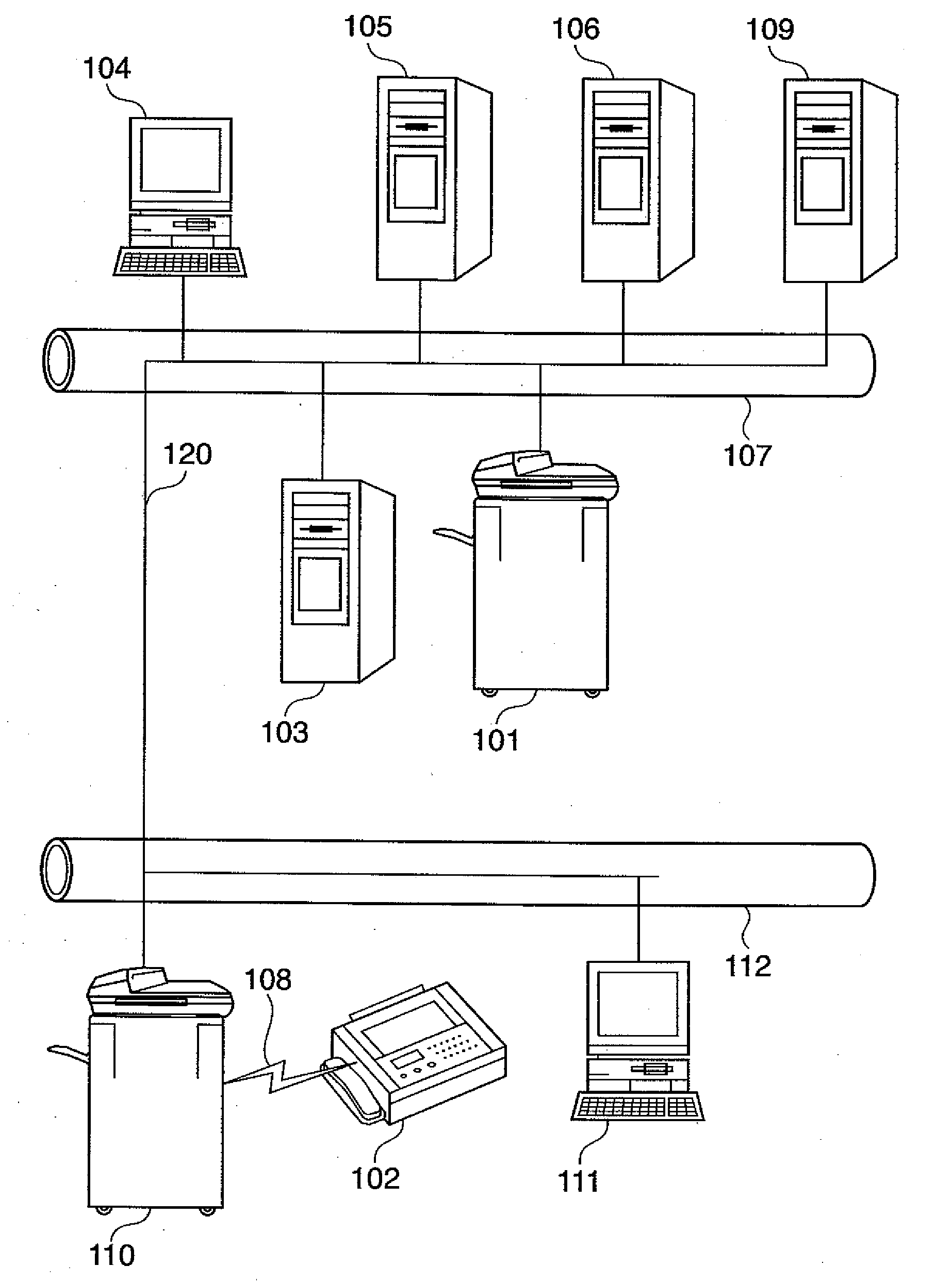
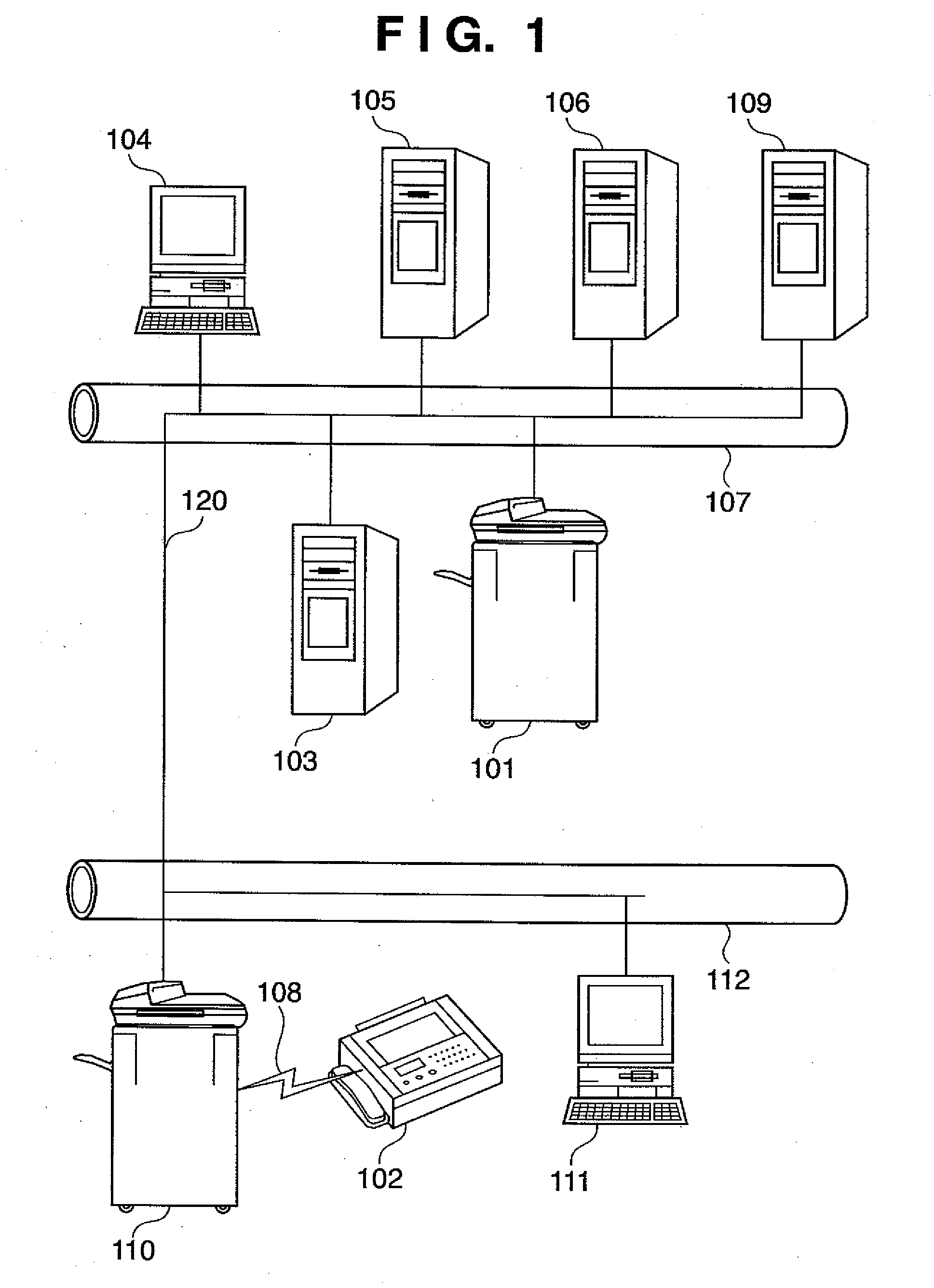
[0028]FIG. 1 is a view of an illustrative arrangement of an image processing system according to an embodiment. Each of multi function peripherals 101 is an image processing apparatus which performs the process of reading, copying, or printing a document, transmits image data to various devices, and receives image data from the various devices. Any of document reading processing for converting into a file, copying, or transmitting image data, the process of receiving a print job and rasterizing it to create image data, the process of receiving image data, and the process of reading out image data from a storage device is an example of the process of acquiring image data.

[0029]A database / mail server 103 is a computer which stores data acquired by each multi function peripheral 101, and a server program which performs storage processing is running on the database / mail server 103. A client computer 104 is a computer which connects to the database / mail server 103 to download and display...

second embodiment

[0044]In this embodiment, the running of an arbitrary job to the storage of a history record will be explained.

[0045]FIG. 4 is an illustrative block diagram of a multi function peripheral according to the embodiment. A control unit 400 connects to a scanner 470 serving as an image input device and a printer 490 serving as an image output device and also connects to a LAN 411 and public telephone line (WAN) 412, thereby inputting or outputting image information or device information. A CPU 401 is a controller which controls the entire system. RAM 402 is a system work memory for the operation of the CPU 401 and also functions as image memory for temporarily storing image data. ROM 403 is a boot ROM in which a system boot program is stored. A hard disk drive (HDD) 404 is a storage device which stores a system control program, image data for security chasing, and the like.

[0046]An operation unit I / F 406 is an interface circuit which connects an operation unit (e.g. UI: User Interface) 4...

third embodiment

[0065]As the format of image data to be stored in a storage server 105, an existing format or unique format may be adopted. This embodiment will explain an example wherein image data is compressed using a unique format.

[0066]FIG. 9 is a diagram showing an example of an image format according to the embodiment. This embodiment will explain the format of an image file with an example wherein a multi function peripheral 110 transfers, by fax, image data 901 received from a facsimile 102 to a multi function peripheral 101.

[0067]The first document 901 indicates a facsimile image received from the facsimile machine 102 by the multi function peripheral 110. The first document 901 is composed of a first header 902, body 903, and first footer 904. A second document 911 indicates image data received from the multi function peripheral 110 by the multi function peripheral 101. The second document 911 is composed of a second header 912, the body 903, and a second footer 914. The first document 9...


PUM


Abstract

This invention uses a storage device more effectively than ever before to store image data in a predetermined storage device for future security chasing. A determination unit (203) determines whether related image data which can be considered substantially identical to image data acquired by an acquisition unit (210) is stored in a predetermined storage device (202) for future chasing. If related image data is stored, link information to the related image data is written instead of writing the acquired image data to the storage device (202). On the other hand, no related image data is stored, the acquired image data is written to the storage device (202).

Description

TECHNICAL FIELD[0001]The present invention relates to a technique for storing image data useful in chasing the cause of leaking-out of secret information and the like.BACKGROUND ART[0002]The wide diffusion of image processing apparatuses has enabled anyone to easily copy or transmit a document. This has offered the user an increase in convenience but at the same time has increased the possibility of information leaking-out such as copying or transmission of a confidential document or the like.[0003]To cope with the problem, there is proposed an image processing apparatus which accumulates, in a storage device, all of image data to be copied or transmitted in addition to a user ID (National Publication of International Patent Application No. 1998-503901). This makes it possible to chase to find out which user has copied or transmitted a document with leaked-out information.DISCLOSURE OF INVENTION[0004]However, the above-described image processing apparatus is configured to accumulate...

Claims


Application Information

Patent Timeline
Patent Type & Authority Applications(United States)
IPC IPC(8): G06F3/12G06K15/00
CPCG06F17/30247Y10S707/915H04N1/00204H04N1/00244H04N1/00323H04N1/00344H04N1/00843H04N1/00862H04N1/00877H04N1/2166H04N1/2187H04N2201/0039H04N2201/3226H04N2201/323H04N2201/3249G06F17/3028G06F16/51G06F16/583
Inventor SHIMADA, BUNGO
Owner CANON KK
Why Eureka
Try Eureka