Flow sensor

a flow sensor and flow rate sensor technology, applied in the field of flow meters, can solve the problems of inability to measure, inability to detect with good accuracy, and inability to detect minute leakage flow rates of approximately 5 l/h, so as to achieve easy detection of minute flow rates and increase the sensitivity of detection by the flow rate sensor

Inactive Publication Date: 2009-01-08
YAMATAKE HONEYWELL CO LTD
View PDF8 Cites 16 Cited by
  • Summary
  • Abstract
  • Description
  • Claims
  • Application Information

AI Technical Summary

Benefits of technology

[0014]With a flow meter having the above-described basic configuration, the ratio of flow diverted among a first flow path and a second flow path provided in parallel changes passively according to the flow rate of fluid flowing through a main flow path. Accordingly, in the case when, for example, the fluid flowing through the main flow path is small, the flow diversion ratio for the first flow path has a high value, and as the flow of fluid through the main flow path increases, the flow diversion ratio for the first flow path decreases, and the provision of a flow rate sensor in the first flow path enables that flow rate sensor to detect flows ranging from minute flow rates to large flow rates.
[0015]Namely, in the above case, causing nearly all of the aforementioned fluid to flow through the first flow path when the flow rate through the main flow path is minute enables that minute flow rate to be detected reliably, and causing the majority of that fluid to flow through the second flow path when the flow rate is large enables the flow rate through the first flow path to be constrained. Accordingly, as the fluid flow rate through the main flow path increases, since the flow rate through the first flow path can be constrained in accordance with the above-described flow diversion ratio, all flows—from minute flow rates to large flow rates—can be detected without causing saturation of the flow rate sensor.
[0016]Moreover, in the aforementioned first flow path, after securing an inlet zone for the aforementioned fluid flow, if a narrow area that constricts the cross-sectional area of that flow path is provided and if the aforementioned flow rate sensor is incorporated into this narrow area, the flow velocity of the minute flow guided to the first flow path can be sped-up in the aforementioned narrow area. As a result, the sensitivity of detection by the flow rate sensor can be increased substantially, and minute flow rates can be detected easily. In particular, the abovementioned narrow area acts as a flow path resistance for large flow rates and is therefore extremely effective for passively changing the flow diversion ratio among the first and second flow paths. Moreover, the abovementioned mesh element, the grid element, and the paddle mechanism act as flow path resistances for minute flow rates and are therefore extremely effective for passively changing the flow diversion ratio among the first and second flow paths.

Problems solved by technology

As the detection sensitivity to minute flow rates is increased as described above, detection sensitivity to large flow rates will also increase, causing a problem in that during the throughflow of a large flow rate, the output of the flow rate sensor will saturate, making measurement impossible.
For this reason, in a gas meter or the like having a maximum measurable flow rate of approximately 30,000 L / h, for example, minute leakage flow rates of approximately 5 L / h were difficult to detect with good accuracy.

Method used


Image

  • Flow sensor
  • Flow sensor
  • Flow sensor

Examples


Embodiment Construction

[0036]The flow meter of the present invention is described below with reference to drawings. The term “fluid” is used throughout the specification and is defined as a liquid, a gas, or both depending on the context. Further, the fluid can be Newtonian or non-Newtonian.

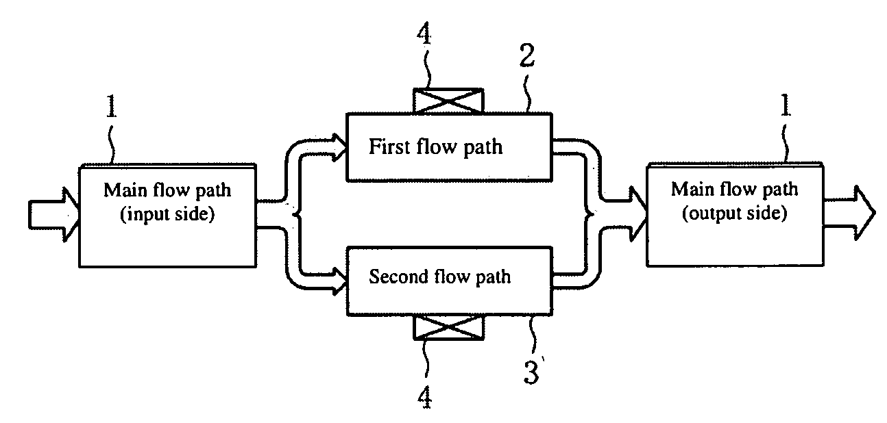
[0037]This flow meter is configured as a suitable gas meter using a thermal type flow rate sensor that detects the mass flow rate of a gas flow, for example. Although not expressly shown, the aforementioned thermal type flow rate sensor is comprised, for example, of a pair of thermosensitive resistive elements provided in the direction of fluid flow between heat-generating resistive elements and mounted on a thin diaphragm formed on a silicon or glass substrate, and is configured so as to detect the flow rate (flow velocity) of the aforementioned fluid from changes in the distribution of temperature near the sensor surface due to the flow of fluid along the sensor surface.

[0038]FIG. 1 shows the basic configuration of t...


PUM


Abstract

The flow meter is equipped with first and second flow paths, provided in parallel and through which flows fluid having flowed through and being diverted from a main flow path, the flow diversion ratio among the first and second flow paths changing passively in accordance with the flow rate of fluid through the main flow path, and a flow rate sensor provided on at least one of the first and second flow paths. The first and second flow paths are formed, for example, as flow paths having different flow path cross-sectional areas, or alternatively are formed from mesh elements provided with mesh-free areas on a portion thereof. Alternatively, one of the either the first or second flow path is realized with a paddle mechanism incorporated therein.

Description

CROSS REFERENCE TO RELATED APPLICATIONS[0001]The present application claims priority under 35 U.S.C. §119 to Japanese Patent Application No. 2007-178359, filed Jul. 6, 2007. The contents of the application is incorporated herein by reference in its entirety.TECHNICAL FIELD[0002]The present invention relates to a flow meter wherein the flow path structure is improved so as to increase the detection sensitivity of a flow rate sensor to minute flow rates, and the detection sensitivity to large flow rates is reduced so as to expand the dynamic range of measurement with the aforementioned flow rate sensor.BACKGROUND OF THE INVENTION[0003]In a flow meter that uses a thermal type flow rate sensor, it has been proposed to increase the detection sensitivity thereof, to compartmentalize the interior of a flow path having a flow rate sensor attached to a wall surface thereof to detect minute flow rates into a plurality of flow paths along the direction of fluid flow so as to increase the flow ...

Claims


Application Information

Patent Timeline
Patent Type & Authority Applications(United States)
IPC IPC(8): G01F5/00
CPCG01F1/00G01F1/6842G01F15/00G01F15/12G01F15/14
Inventor NIIKAWA, KOICHIROOOISHI, YASUHARUSEO, MASAKI
Owner YAMATAKE HONEYWELL CO LTD
Why Eureka
Try Eureka