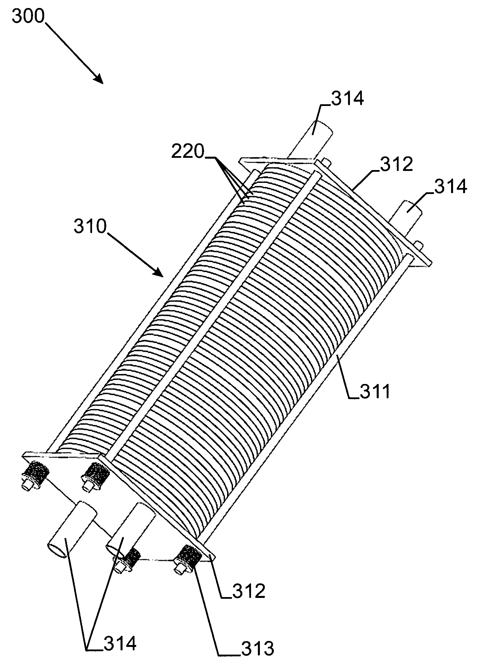
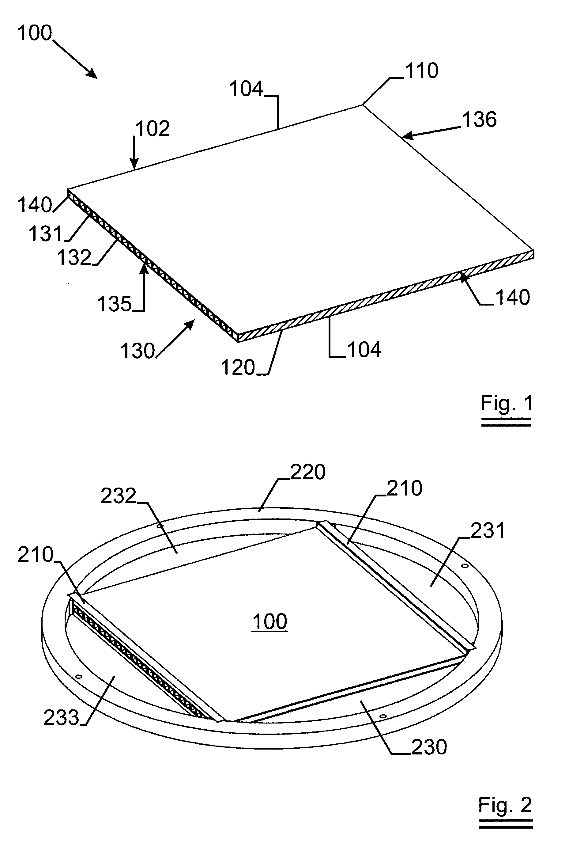
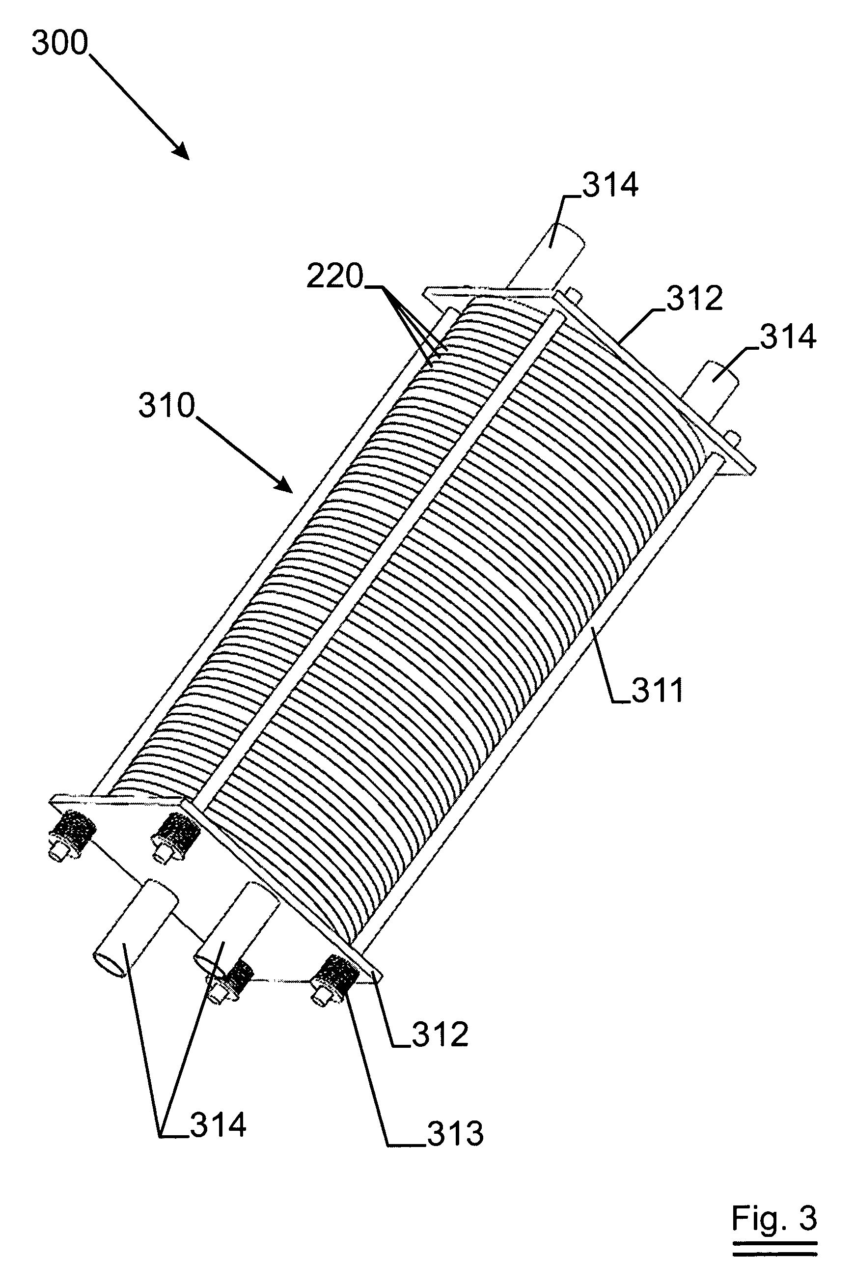
Filter Plate for Use in a Filter Stack

a filter plate and stack technology, applied in the field of filter plates, can solve the problems of damage to the interior of the plate, significant downtime of the press filter, and difficulty in assembling and dismantling, and achieve the effect of less vulnerable to defects

Inactive Publication Date: 2009-01-08
NV BEKAERT SA
View PDF8 Cites 10 Cited by
  • Summary
  • Abstract
  • Description
  • Claims
  • Application Information

AI Technical Summary

Benefits of technology

[0007]It is an object of the present invention to provide an alternative filter plate and methods of making the same, for use in filter systems such as filter presses, back washing filter systems, back pulsing filter systems or back flushing filter systems. It is an advantage of some embodiments of the present invention to provide a filter plate, which comprises fewer spare parts as the presently known filter plates. It is also an advantage of some embodiments of the present invention t...

Problems solved by technology

Assembling and dismantling requires a significant amount of time, is labour intensive and causes a significant downtime for the press filter.
Due to vibrations, shocks or changing fluid pressure, the mesh or expanded plate may dislocate and thereby damage the interior of the plate, i.e. the membrane.
The mesh also creates a pressure drop over the filter plate, which both reduces the yield of filtrate obtained using given filtration pressure, and makes back washing, back flushing or back pulsing difficult if not impossible.
However, in several filter systems, as an example but not limited to filter pre...

Method used


Image

  • Filter Plate for Use in a Filter Stack
  • Filter Plate for Use in a Filter Stack
  • Filter Plate for Use in a Filter Stack

Examples


Embodiment Construction

[0067]The present invention will be described with respect to particular embodiments and with reference to certain drawings but the invention is not limited thereto but only by the claims. The drawings described are only schematic and are non-limiting. In the drawings, the size of some of the elements may be exaggerated and not drawn on scale for illustrative purposes. The dimensions and the relative dimensions do not correspond to actual reductions to practice of the invention.

[0068]Furthermore, the terms first, second, third and the like in the description and in the claims, are used for distinguishing between similar elements and not necessarily for describing a sequential or chronological order. It is to be understood that the terms so used are interchangeable under appropriate circumstances and that the embodiments of the invention described herein are capable of operation in other sequences than described or illustrated herein.

[0069]Moreover, the terms top, bottom, over, under...


PUM

PropertyMeasurementUnit
Pore sizeaaaaaaaaaa
Flow rateaaaaaaaaaa
Diameteraaaaaaaaaa

Abstract

A filter plate for filtration (100) of a fluid as subject of the present invention comprises a first filter membrane (110) and a second filter membrane (120). The filter membranes are substantially planar and substantially-parallel. The filter membranes comprise metal fibers. The filter plate comprises a reinforcing means (130, 131) interposed between the filter membranes. The first and second filter membrane are attached to the reinforcing means. The reinforcing means creates at least two flow channels (132) between the filter membranes for guiding a fluid towards the edge of the filter plate.

Description

TECHNICAL FIELD OF THE INVENTION[0001]The present invention relates to filter plates, and more in particular to filter plates and filter stacks for use in a filter system as well as to methods of manufacturing such filter plates.BACKGROUND OF THE INVENTION[0002]Filter systems using filter plates are well known in the art. As an example, a filter press is described in WO2005 / 028070. A number of filter membranes are stacked together with means to create chambers at each side of the filter membrane for receiving fluid to be filtered or for evacuation of filtrate. The stacking of membranes and means for creating chambers is to be done very accurately and carefully in order to avoid leakage and / or mixing of filtrate with fluid to be filtered. Dismantling of the press filter is to be done quite often in order to clean the press filter, when the filter is clogged with particles retained from the fluid. Assembling and dismantling requires a significant amount of time, is labour intensive an...

Claims


Application Information

Patent Timeline
IPC IPC(8): B01D25/12
CPCB01D25/26B01D39/12B01D39/2041B01D46/10B01D2313/14B01D2239/0654B01D2275/10B01D2313/08B01D63/082B01D63/0822
Inventor VERHAEGHE, JOHNHUGELIER, JOHANVAN HAEKE, MARTINVAN MEENEN, JOHAN
Owner NV BEKAERT SA
Why Eureka
Try Eureka