Light-Receiving Device

Inactive Publication Date: 2009-01-08
SUMITOMO BAKELITE CO LTD
View PDF12 Cites 12 Cited by
  • Summary
  • Abstract
  • Description
  • Claims
  • Application Information

AI Technical Summary

Benefits of technology

[0017]Next, a method for manufacturing the above-described light-receiving device will be described. On a semiconductor substrate including the light receiving element having microlenses 3 disposed corresponding to each of the photo acceptance regions formed thereon and surface electrodes formed in regions except the regions having microlenses, a cyclic olefin resin having epoxy group and a resin composition containing a crosslinker are applied by employing a spin coater and are dried to obtain a coating film. Further, a transparent cover is disposed on such coating film, and then the entire thereof is heated to a temperature of 50 degree C. to 250 degree C. to join thereof. As such, the light-receiving device as shown in FIG. 1 is obtained.
[0018]An epoxy resin is often conventionally employed for the above-described sealing member 5 in place of a cyclic olefin resin having epoxy group, and smaller difference in a refractive index between the light receiving element and the epoxy resin may causes a problem of losing focusing function, when the light receiving element is protected so as to be directly embedded in contact with the epoxy resin. Further, a problem of reducing a light-receiving ratio of the light receiving element may be occurred due to a deterioration of the epoxy resin on the light receiving element caused by a light for a long-term use.
[0019]In the present invention, a cyclic olefin resin having epoxy group is employed for the sealing member, so that the above-described deterioration of the resin can be considerably inhibited, and a suitable difference in the refractive index between the light receiving element and the epoxy resin can be ensured, leading to achieving a continuous sustainment of the focusing ability.
[0020]FIG. 2 is a diagram, showing a schematic structure of a light receiving element according to the present embodiment. Such light receiving element includes a substrate 1, a light receiving element 2 provided on a surface of the substrate 1 and a transparent cove

Problems solved by technology

This may cause a haze in a surface of the light receiving elem

Method used


Image

  • Light-Receiving Device
  • Light-Receiving Device
  • Light-Receiving Device

Examples


first embodiment

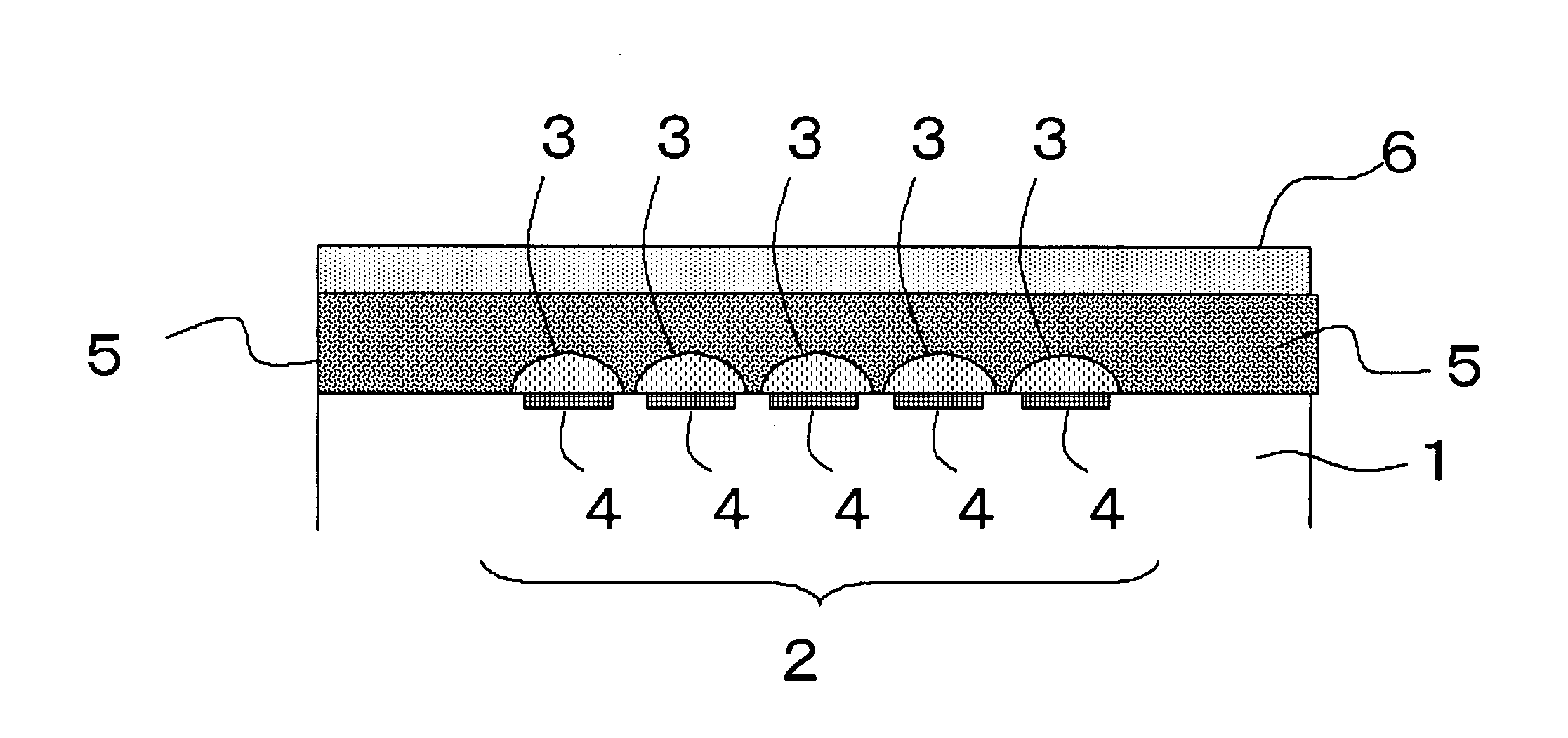
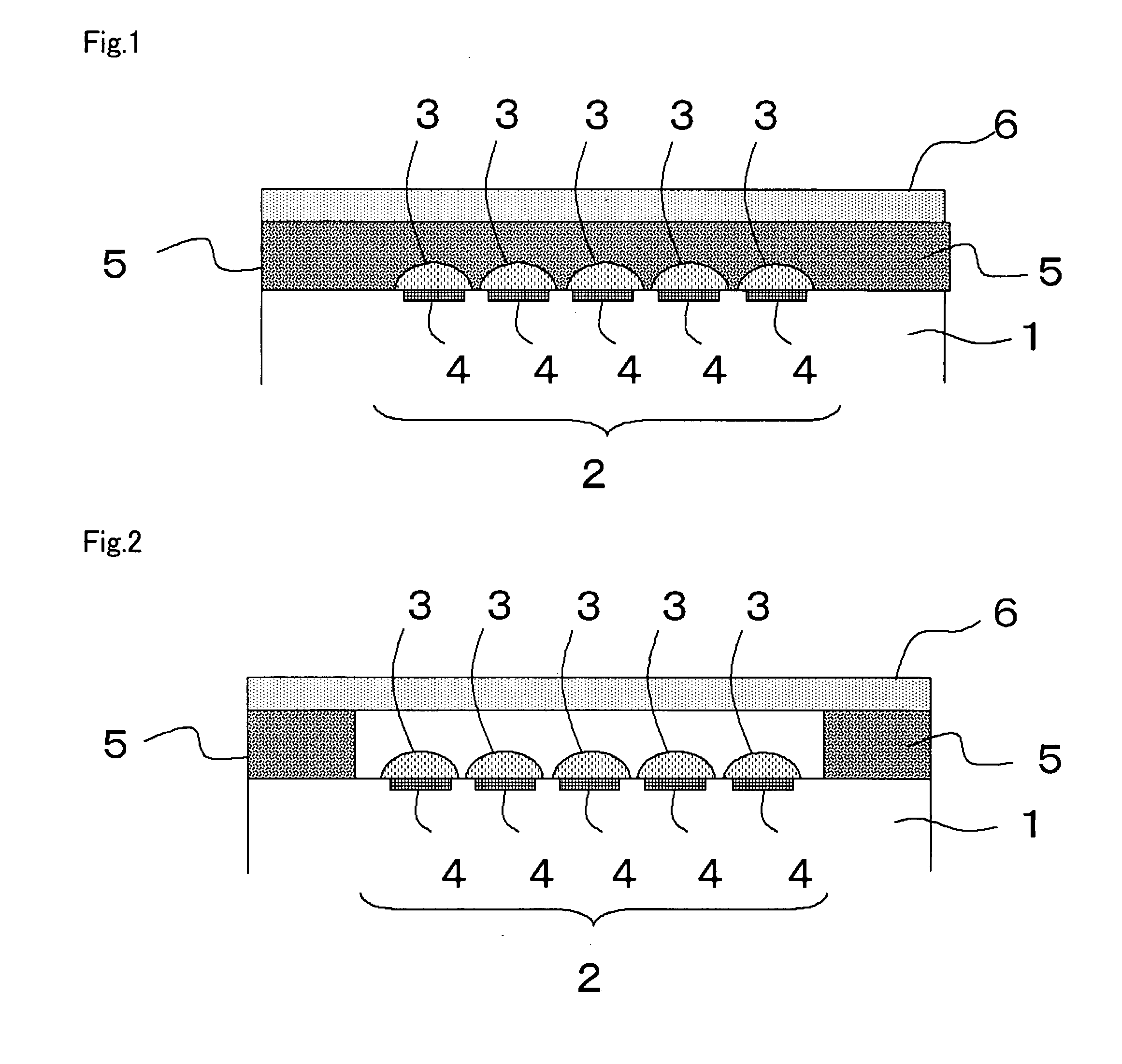
[0014]FIG. 1 is a diagram, showing a schematic structure of a light receiving element according to the present embodiment. Such light receiving element includes a substrate 1, a light receiving element 2 provided on a surface of the substrate 1, a transparent cover 6 provided above such surface, and a sealing member 5, which is provided to fill a gap between the substrate 1 and the transparent cover 6 and adopted for providing a seal for the light receiving element 2 from the exterior thereof. The sealing member 5 is composed of a material containing a cyclic olefin resin. The light receiving element 2 on the support 1 is presented by a two-dimensional array of pixel sensors composed of photoelectric regions 4 and microlenses 3, and this may alternatively have a standard configuration. An image resolution that the image sensor can be achieved is determined by the sizes and number of the pixel sensors, and the arrangement thereof ordinarily includes several hundreds to several thousa...

second embodiment

[0020]FIG. 2 is a diagram, showing a schematic structure of a light receiving element according to the present embodiment. Such light receiving element includes a substrate 1, a light receiving element 2 provided on a surface of the substrate 1 and a transparent cover 6 provided above the surface thereof. A sealing member 5 composed of a material containing a cyclic olefin resin is provided between the substrate 1 and the transparent cover 6. The sealing member 5 is provided to surround the light receiving element 2 in a position remote from the light receiving element 2, and joins the substrate 1 with the transparent cover 6 and has a hollow portion formed in the inner side thereof. The sealing member 5 is composed of a material containing a cyclic olefin resin.

[0021]The sealing member 5 functions as a spacer (dam) for forming a hollow structure between the transparent cover 6 and the light receiving element 2. The sealing member 5 may be joined to the transparent cover 6 through t...

third embodiment

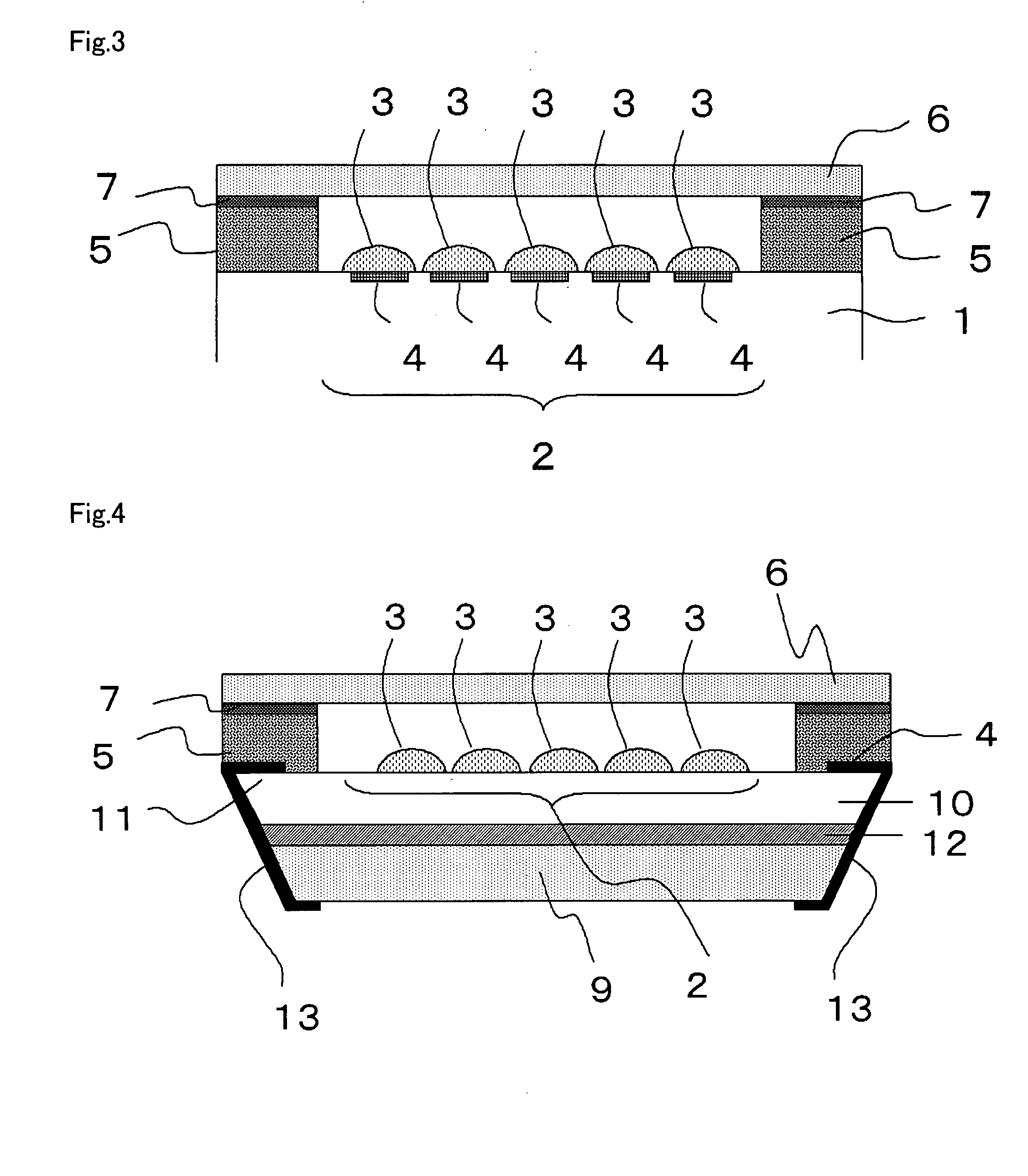
[0024]FIG. 3 and FIG. 4 are diagrams, showing a schematic structure of a light receiving element according to the present embodiment. FIG. 4 shows a cross-sectional view of a CMOS image sensor, which has a wafer level chip size package (CSP) structure that is a type of a light-receiving device shown in FIG. 3 and has a hollow structure of the present invention.

[0025]In the light-receiving device according to the present embodiment, the sealing member 5 is disposed so as to surround the light receiving element 2 to join the substrate 1 with the transparent cover 6, and has a hollow portion formed in the inner side thereof. An upper portion of the sealing member 5 has a flat geometry, and a transparent cover is provided on the surface thereof through an adhesive agent 7, as required. The sealing member 5 is higher than the microlenses 3, and if the transparent cover 6 is provided on the upper surface of the sealing member 5, an air gap is formed between the microlenses 3 and the trans...


PUM


Abstract

Disclosed is a light-receiving device comprising a substrate provided with at least one light-receiving element and a transparent cover (6) arranged above the surface of the substrate on which the light-receiving element is formed. A sealing member (5) is provided between the substrate and the transparent cover (6) at least in the region of the substrate surrounding the light-receiving element. This sealing member (5) is composed of a material containing cyclic olefin resin.

Description

TECHNICAL FIELD[0001]The present invention relates to a substrate provided with a light receiving element, a sealing member and a light-receiving device comprising a transparent cover.BACKGROUND ART[0002]Since a light receiving element is required to precisely capture incident light in a light-receiving device, it is needed to isolate thereof from an external atmospheric air such as moisture air and the like. Here, a transparent cover of a glass plate or the like is generally provided above the light receiving element, and the light receiving element is isolated from the external atmospheric air by a manner described below.[0003]Typically known methods for protecting the light receiving element from the exterior include a method for shielding against an external moisture by filling the light receiving element region with a resin and in addition include a method for shielding against an external moisture by surrounding a circumference of a light receiving element region with a resin ...

Claims


Application Information

Patent Timeline
IPC IPC(8): H01L31/113
CPCH01L23/3192H01L27/14618H01L27/14627H01L31/0203H01L2924/0002H01L2924/3025H01L2924/00H01L23/02H01L23/10
Inventor KUSUNOKI, JUNYAHIRANO, TAKASHI
Owner SUMITOMO BAKELITE CO LTD
Why Eureka
Try Eureka