
System and method for implementation motion-driven multi-shot image stabilization

a multi-shot image and motion-driven technology, applied in the field of camera modules, can solve the problems of image stabilization, image stabilization, and degradation of the final image, and achieve the effects of reducing the computational cost of processing many image shots and the memory requirements

Active Publication Date: 2009-01-08
NOKIA TECHNOLOGLES OY
View PDF7 Cites 56 Cited by
  • Summary
  • Abstract
  • Description
  • Claims
  • Application Information

AI Technical Summary

Benefits of technology

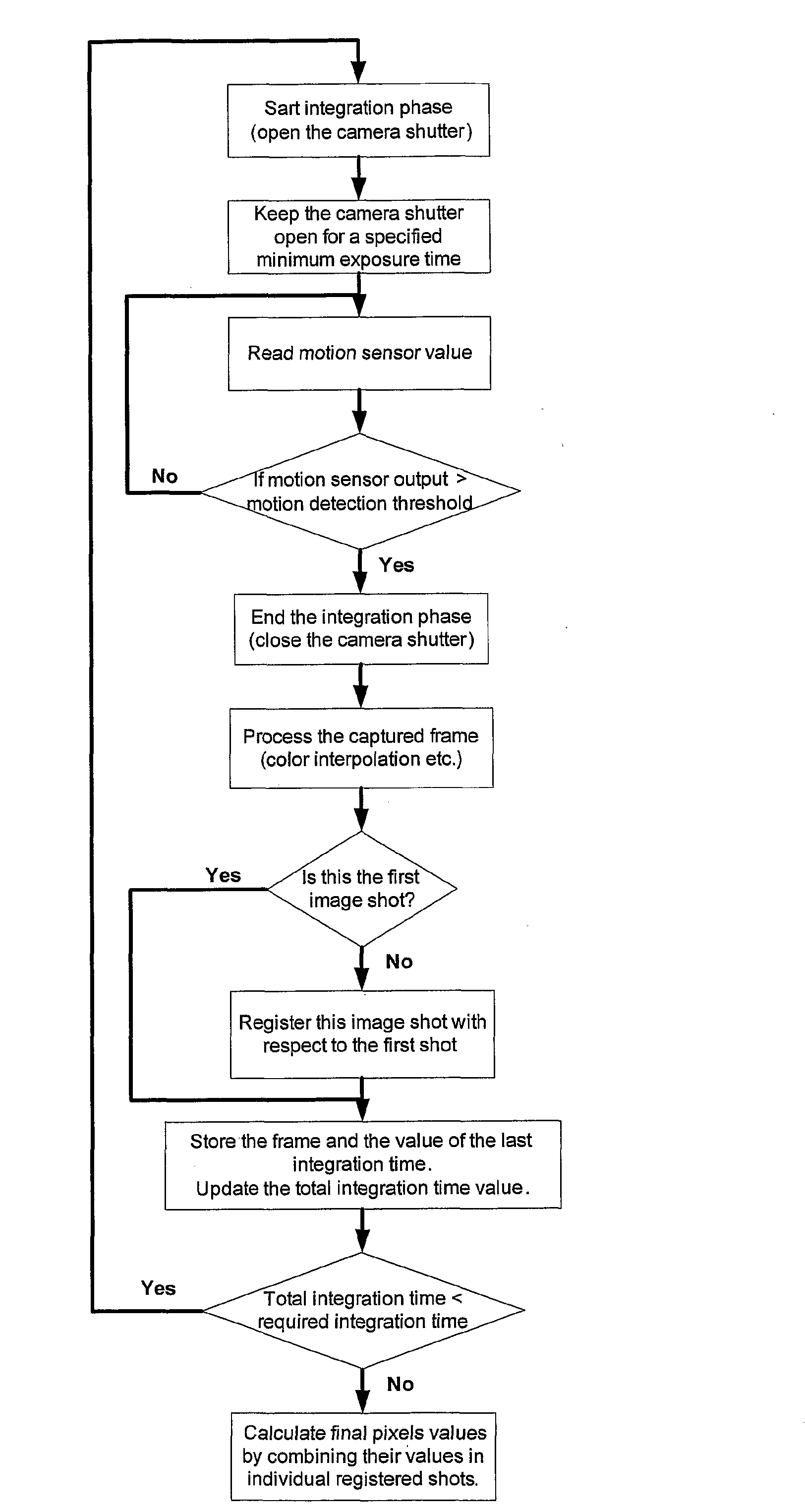
[0015]The present invention provides for a number of substantial advantages not available in conventional systems. With the present invention, there is no need to use expensive motion sensors, as the motion must be only detected and not measured. Simple motion sensors can provide very good results for this purpose. For example, accelerometers are much smaller and less expensive than gyroscopes and therefore could be particularly useful for the purpose of the invention. It also may be possible to use two or more accelerometers distributed along the device's borders in order to sense rotational motion in addition to linear translation.
[0016]With the present invention, the number of image shots captured during exposure is reduced to a minimum, reducing the computational cost of processing many image shots and the memory requirements compared to the classical multi-shot approach. In addition, the present invention allows for the adjustment of the level of the motion detection threshold in accordance with the state of the system. For example, the threshold could be adjusted in accordance to the zoom ratio used when capturing the image. Therefore, when using a large zoom ratio, a small threshold would be needed because even a small motion could cause a significant shift of the image projected onto the image sensor. On the other hand, when using a zoom ×1, the same motion could result in a very small shift, which does not justify the interruption of the exposure time for the current frame.
[0017]The system and method of the present invention possesses all of the advantages of the multi-shot technique described above. In particular, the use of the present invention results in a small level of noise sensitivity, and the present invention does not require the system to apply inverse filtering to restore the image. At the same time, the present invention possesses the advantages of the single shot technique, namely the small memory requirements and low computational cost due to the small number of captured image shots.

Problems solved by technology

Since the beginning of photography, image stabilization has been a consistent issue.
The problem of ensuring that a photograph is not blurred due to camera movement has remained an issue even as camera technology has progressed to the present day.
In digital cameras, the problem of image stabilization stems from fact that any known image sensor needs to have the image projected on it during a period of time referred to herein as integration time.
Any motion of the camera during this time causes a shift of the image projected on the sensor, resulting in a degradation of the final image.
One of the principal difficulties in restoring motion blurred images involves the fact that the motion blur is different in each degraded image.
The first factor is the inherent difficulty in avoiding unwanted motion during the integration time when using a small hand-held device, such a camera telephone.
Consequently, this approach may require expensive motion sensors (i.e., in the form of gyroscopes), which are also large in size and therefore difficult to include in small devices.
In addition, if the exposure time is large, then the position information derived from the motion sensor output exhibits a bias drift error with respect to the true value.
The bias drift error accumulates over time such that the outcome of the process can be significantly corrupted over time.
However, this solution also suffers from system drift error and is therefore not practical for long exposure times.
Although resolving some of the issues discussed above, multi-shot solutions require a large amount of computational resources in order to capture several high resolution frames during a short interval of time.
In addition, these methods also require a large amount memory in order to store the captured image shots before the pixel fusion step.
This can be especially expensive to implement in smaller devices where memory resources may be quite limited.

Method used


Image

  • System and method for implementation motion-driven multi-shot image stabilization
  • System and method for implementation motion-driven multi-shot image stabilization
  • System and method for implementation motion-driven multi-shot image stabilization

Examples


Embodiment Construction

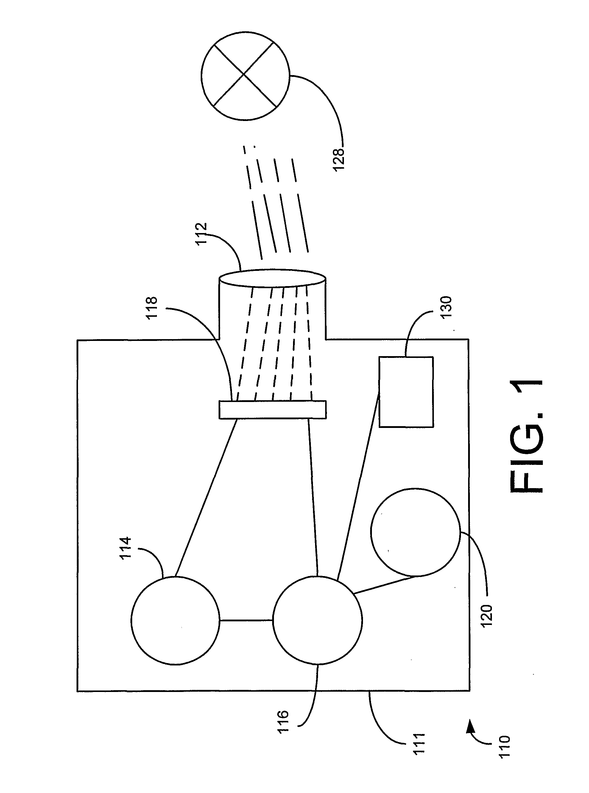
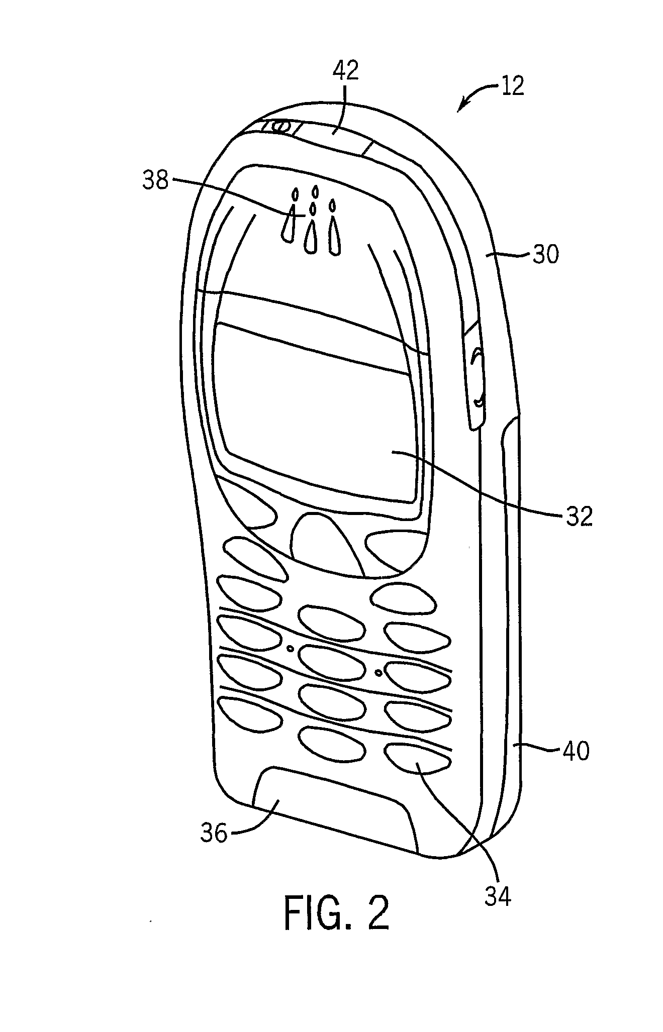
[0024]A generic camera module constructed according to the principles of the present invention is shown at 110 in FIG. 1. The camera module 110 can be a stand-alone device or can be incorporated into another electronic device, such as a portable telephone. The camera module 110 includes a housing 111 which contains at least one lens 112, a primary memory unit 114, a camera processor 116, and at least one image sensor 118. The primary memory unit 114 can be used to store digital images and computer software for performing various functions in the camera module 110, as well as to implement the present invention. A removable, secondary memory unit 120 in the form of a memory card can also be included in the digital camera to provide extra memory space. The image sensor 118 can be a charge coupled device (CCD), a complementary metal oxide semiconductor (CMOS), or another system. The camera module 110 also includes at least one motion sensor 130 operatively connected to the camera proces...


PUM


Abstract

An improved system and method for capturing an image using a camera or a camera module. In the present invention, the number of image shots taken, as well as the integration time of each image shot, are controlled based upon knowledge about the existence or absence of camera motion. Whenever a motion is detected above a predetermined motion threshold, the integration phase of the current image shot ends, and the integration of the next image shot begins. The present invention therefore adapts to the actual camera motion during exposure. If there is no camera motion, a single, long exposed image shot is captured. If there is camera motion, the total exposure time is divided between multiple shots in accordance with the degree of camera motion.

Description

FIELD OF THE INVENTION[0001]The present invention relates generally to the field of cameras and camera modules. More particularly, the present invention relates to systems for improving image stabilization in cameras and camera modules.BACKGROUND OF THE INVENTION[0002]Since the beginning of photography, image stabilization has been a consistent issue. The problem of ensuring that a photograph is not blurred due to camera movement has remained an issue even as camera technology has progressed to the present day. In digital cameras, the problem of image stabilization stems from fact that any known image sensor needs to have the image projected on it during a period of time referred to herein as integration time. Any motion of the camera during this time causes a shift of the image projected on the sensor, resulting in a degradation of the final image. This degradation is referred to herein as motion blur.[0003]One of the principal difficulties in restoring motion blurred images involv...

Claims


Application Information

Patent Timeline
Patent Type & Authority Applications(United States)
IPC IPC(8): H04N5/232H04N23/68
CPCH04N1/00307H04N5/23248H04N2101/00H04N5/2327H04N5/2625H04N5/23258H04N23/684H04N23/68H04N23/6812
Inventor TICO, MARIUSVEHVILAINEN, MARKKU
Owner NOKIA TECHNOLOGLES OY
Learn More