
Loudspeaker damper, manufacturing method thereof, and loudspeaker and electronic device using the same

a technology of loudspeaker and manufacturing method, applied in the direction of coating, coating, flooring, etc., can solve the problems of gap failure, too much load applied, and loudspeaker may be considerably lowered

Active Publication Date: 2009-01-08
PANASONIC CORP
View PDF6 Cites 9 Cited by
  • Summary
  • Abstract
  • Description
  • Claims
  • Application Information

AI Technical Summary

Benefits of technology

[0013]The present invention has been made in view of the above-described conventional problems. A loudspeaker damper of the present invention includes a material and thermosetting resin including 2 to 20 wt % of flexibility imparting agent, in which the material is impregnated with the thermosetting resin.

Problems solved by technology

H8-340596, too much load is applied, so that minimum resonance frequency (F0) of the loudspeaker may be considerably lowered and gap failure may occur because a vibration system of the loudspeaker cannot be sufficiently supported.
However, there has been a problem that even a loudspeaker damper described in Japanese Patent Unexamined Publication No.
That is to say, when a large input is applied to a loudspeaker and a voice coil and a diaphragm oscillate, a damper prevents the oscillation and a resin layer provided on the surface of the damper base material is cracked due to partial interface peeling.
Thus, the property is deteriorated.

Method used


Image

  • Loudspeaker damper, manufacturing method thereof, and loudspeaker and electronic device using the same
  • Loudspeaker damper, manufacturing method thereof, and loudspeaker and electronic device using the same
  • Loudspeaker damper, manufacturing method thereof, and loudspeaker and electronic device using the same

Examples


first exemplary embodiment

[0039]Hereinafter, a first exemplary embodiment of the present invention is described. Since a configuration of a loudspeaker using a loudspeaker damper is the same as that described with reference to FIGS. 5, 6A and 6B, the description thereof is omitted herein.

[0040]The loudspeaker damper of the first exemplary embodiment is obtained by impregnating a material such as fabric, heat-resistant nylon and polyester with thermosetting resin such as phenolic resin and melamine resin, followed by heat curing the resin impregnated material. The above-mentioned thermosetting resin such as phenolic resin and melamine resin includes 2 to 20% of flexibility imparting agent.

[0041]An example of the flexibility imparting agent used in the present invention includes the following well-known flexibility imparting agents:

[0042](a) isocyanates;

[0043](b) glycidylethers;

[0044](c) natural vegetable oils such as linseed oil, castor oil, tung oil, oiticica oil, and dehydrated castor oil;

[0045](d) addition...

second exemplary embodiment

[0057]Hereinafter, a second exemplary embodiment is described.

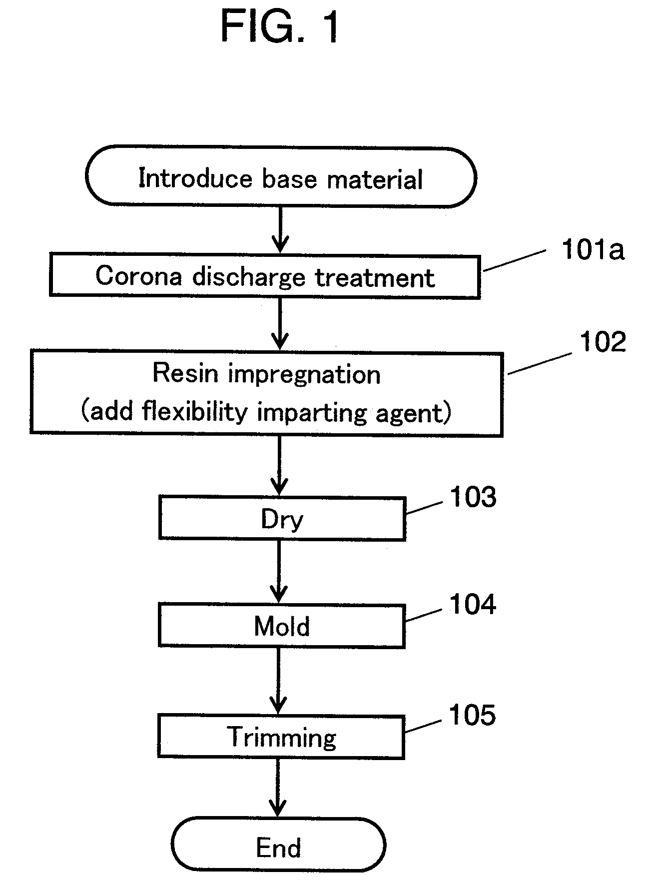
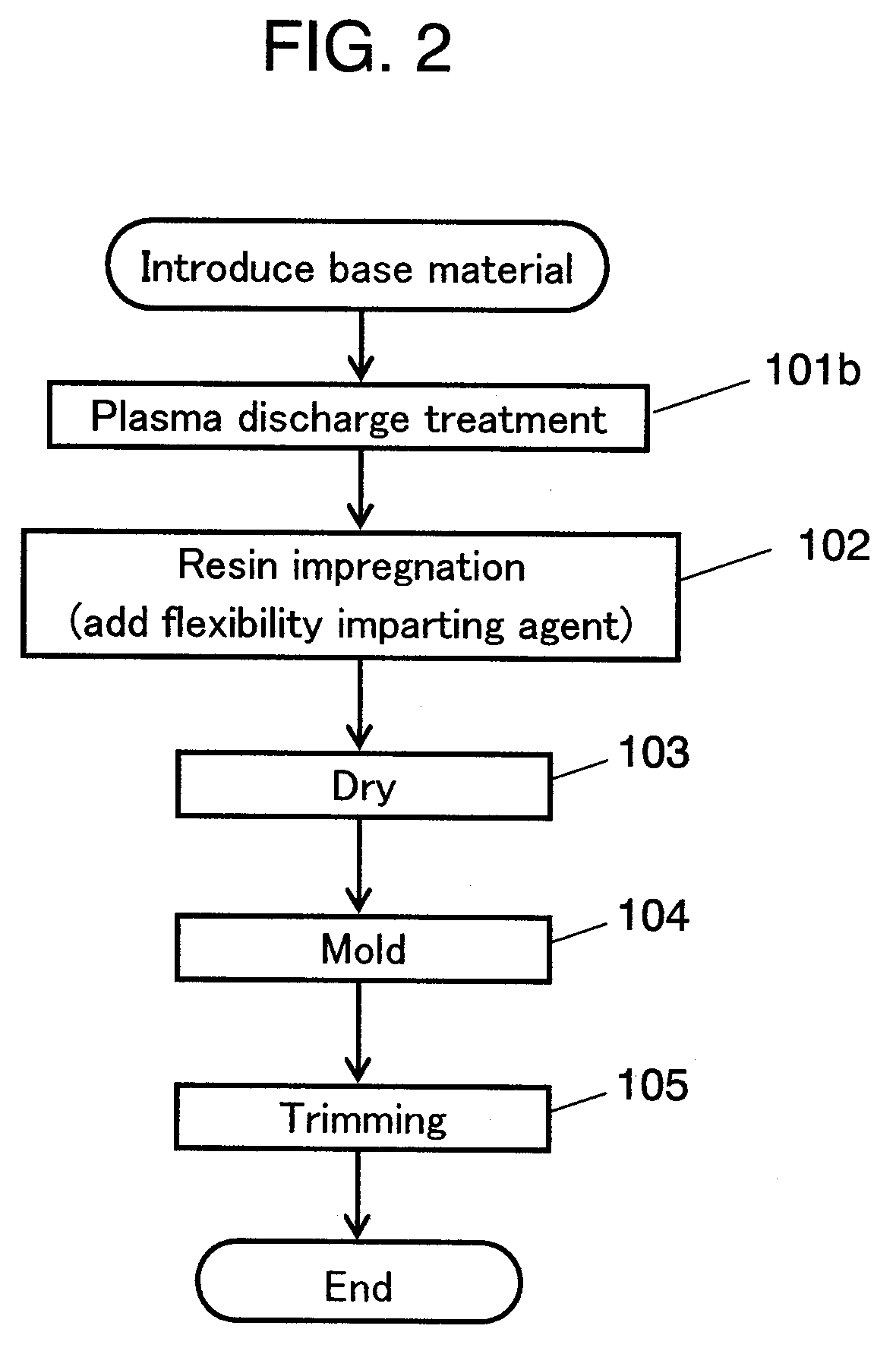
[0058]In this exemplary embodiment, in the manufacturing process of a damper produced in the first exemplary embodiment, before the step of impregnating a damper base material with phenolic resin including 10 wt % of flexibility imparting agent, a material is subjected to corona discharge treatment. The other configuration and manufacturing method are the same as those in the first exemplary embodiment. Therefore, the detailed description of the same portions are omitted and only different portions are described with reference the drawings as follows.

[0059]FIG. 1 is a manufacturing process chart showing a manufacturing method of a loudspeaker damper in accordance with this exemplary embodiment. As shown in FIG. 1, after a base material is introduced, in step 101a, the introduced base material is subjected to corona discharge treatment as a surface treatment process. Next, in step 102, resin impregnation process is carried...

third exemplary embodiment

[0073]Hereinafter, a third exemplary embodiment is described.

[0074]FIG. 3 is an outside view showing an audio minicomponent system in accordance with one exemplary embodiment of the present invention.

[0075]As shown in FIG. 3, a loudspeaker system is configured by incorporating loudspeaker 40 into enclosure 41. Minicomponent system 44 includes amplifier 42 for amplifying electric signals input into this loudspeaker and player 43 for outputting a source input into amplifier 42.

[0076]With such a configuration, it is possible to realize high quality and high reliability of electronic equipment having a wide dynamic range and allowing large output according to the digitization of input.


PUM


Abstract

A loudspeaker damper, a manufacturing method thereof, and a loudspeaker, electronic equipment and device using the loudspeaker damper. The damper has flexibility. Therefore, even if a large input is applied and the damper oscillates with a large amplitude, a resin layer provided on the surface of the damper base material is not cracked due to partial interface peeling. Thus, the damper follows such a large amplitude and realizes high input-resistance. This loudspeaker damper material is obtained by impregnating a material with thermosetting resin including 2 to 20 wt % of flexibility imparting agent and heat-curing thereof.

Description

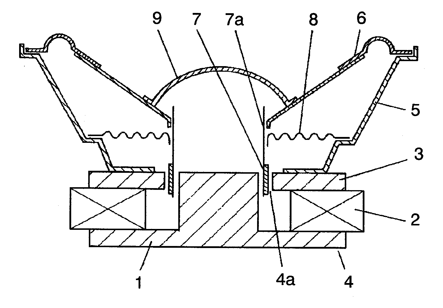
TECHNICAL FIELD[0001]The present invention relates to a loudspeaker damper used in various acoustic equipment, a manufacturing method thereof, and a loudspeaker, electronic equipment and a device using the loudspeaker damper.BACKGROUND ART[0002]FIG. 5 is a sectional view showing a configuration of a loudspeaker; and FIGS. 6A and 6B are a plan view and a sectional view showing a configuration of a damper used in the loudspeaker. With reference to FIGS. 5, 6A and 6B, this loudspeaker is described.[0003]Magnetic circuit 4 including annular magnetic gap 4a is configured by bottom plate 1 having a convex-shaped cross section, ring magnet 2 provided on bottom plate 1, and ring upper plate 3 provided on magnet 2. Such a configuration is referred to as an outer magnet type.[0004]Frame 5 is coupled to upper plate 3. The outer peripheral portion of diaphragm 6 is coupled to frame 5. Voice coil 7 is movably disposed in magnetic gap 4a. As shown in FIG. 5, bobbin 7a on which a coil of voice coi...

Claims


Application Information

Patent Timeline
Patent Type & Authority Applications(United States)
IPC IPC(8): H04R1/00E04B1/82B05D3/06
CPCH04R7/16H04R2499/13H04R2307/201H04R9/043
Inventor OKAZAKI, MASATOSHIMIMURA, KAZUYOSHIMIZONE, SHINYASUMIYAMA, MASAHIDE
Owner PANASONIC CORP
Learn More