Machine for the processing of optical work pieces, specifically of plastic spectacle lenses

a technology for processing machines and spectacle lenses, applied in the field of processing machines for optical workpieces, can solve the problems of compromising machine efficiency, affecting the efficiency of machines, and forming unsatisfactory vapors during the machining of certain highs, and achieves the effects of reducing the number of workpieces

Active Publication Date: 2009-01-08
SATISLOH AG
View PDF29 Cites 13 Cited by
  • Summary
  • Abstract
  • Description
  • Claims
  • Application Information

AI Technical Summary

Benefits of technology

[0021]Furthermore, it is preferred that the work direction of the fast-tool arrangement of the at least one lathe unit is tilted relative to a plane that is substantially perpendicular to the swivel axis, so that the fast-tool arrangement, viewed from the adjusting mechanism, slopes downwardly in the radial outward direction. The mentioned tilt of the fast-tool arrangement firstly allows for a very precise height adjustment of the cutting edge of the lathe tool that is fixed to the fast-tool arrangement in relation to the work piece rotation axis, without the necessity to adjust the height of the lathe tool cutting edge in relation to the fast-tool arrangement. This arrangement eliminates the need for mechanical adjustment systems or the like for the height adjustment of the lathe tool. The amount of feed movement of the work piece spindle in the direction of its axis and thus the height compensation between the work piece rotation axis and the work point of the lathe cutting edge achieved therewith, is provided according to the sine function of the pre-determined angle between the plane that is perpendicular to the swivel axis and the work direction of the fast-tool arrangement. The tilt of the fast-tool arrangement that slopes off in the radial outward direction, provides the advantage that the lathe tool can withdraw in a retracted position with respect to the work space of the machine when the electricity is turned off of the fast-tool arrangement, and remains there in a de-energized state of the fast-tool arrangement, thus reducing the risk that the machine operator cuts himself on the very sharp lathe cutting edge during setting operations or the like in the workspace of the machine.
[0022]In accordance with another aspect of the invention, a covering hood can be mounted to a swing table of the swivel drive unit, that covers the work piece spindle and the linear drive unit at the same time, which has the advantage that no separate sealing or protective measures are necessary.
[0023]In this embodiment, the covering hood can have an opening through which the work piece spindle moveably extend

Problems solved by technology

In addition, unpleasant vapors may be formed during the machining of certain high index materials that should be removed by suction and filtered.
The shield is relatively large and expensive because the X-axis i

Method used


Image

  • Machine for the processing of optical work pieces, specifically of plastic spectacle lenses
  • Machine for the processing of optical work pieces, specifically of plastic spectacle lenses
  • Machine for the processing of optical work pieces, specifically of plastic spectacle lenses

Examples


Embodiment Construction

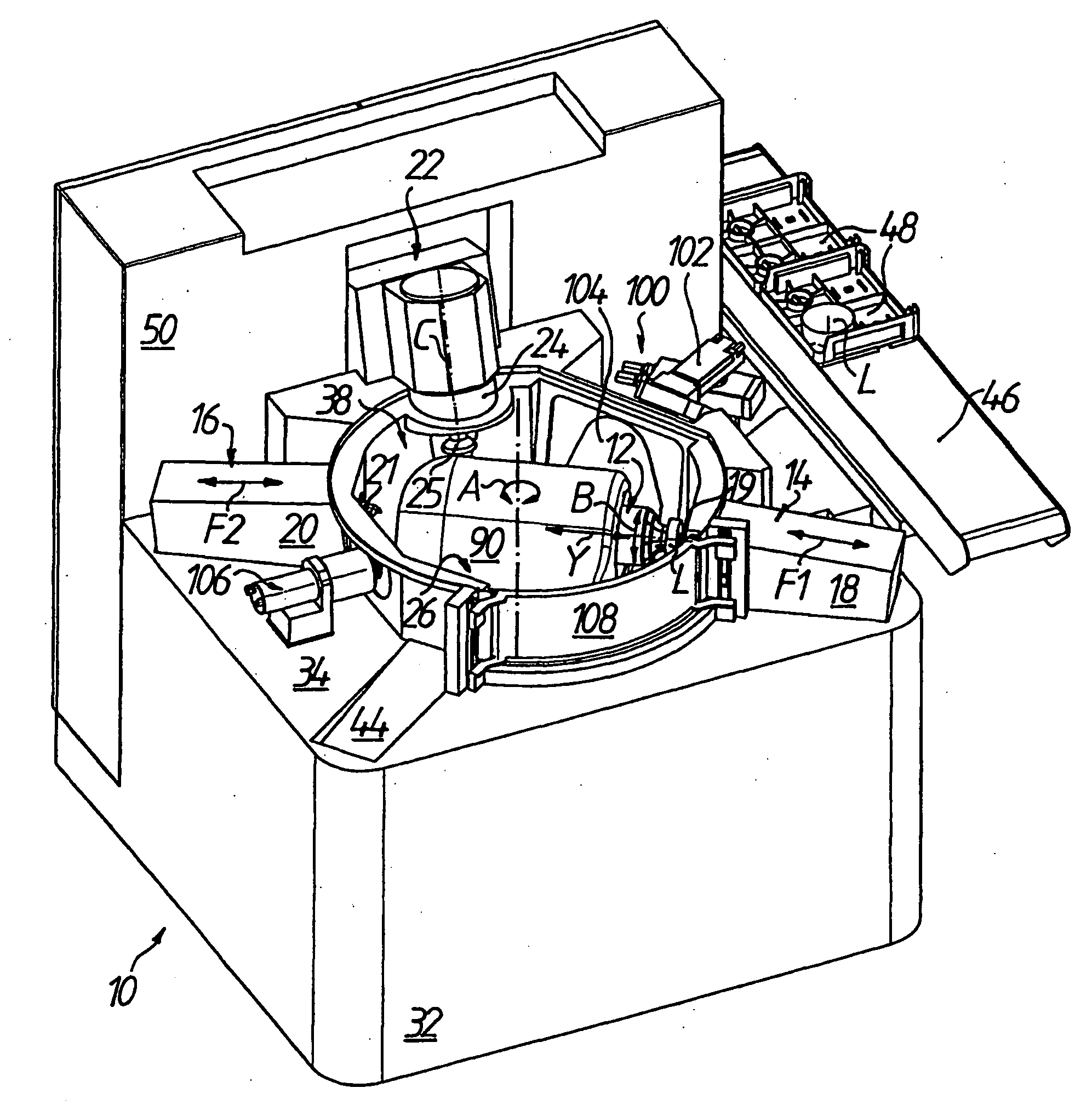
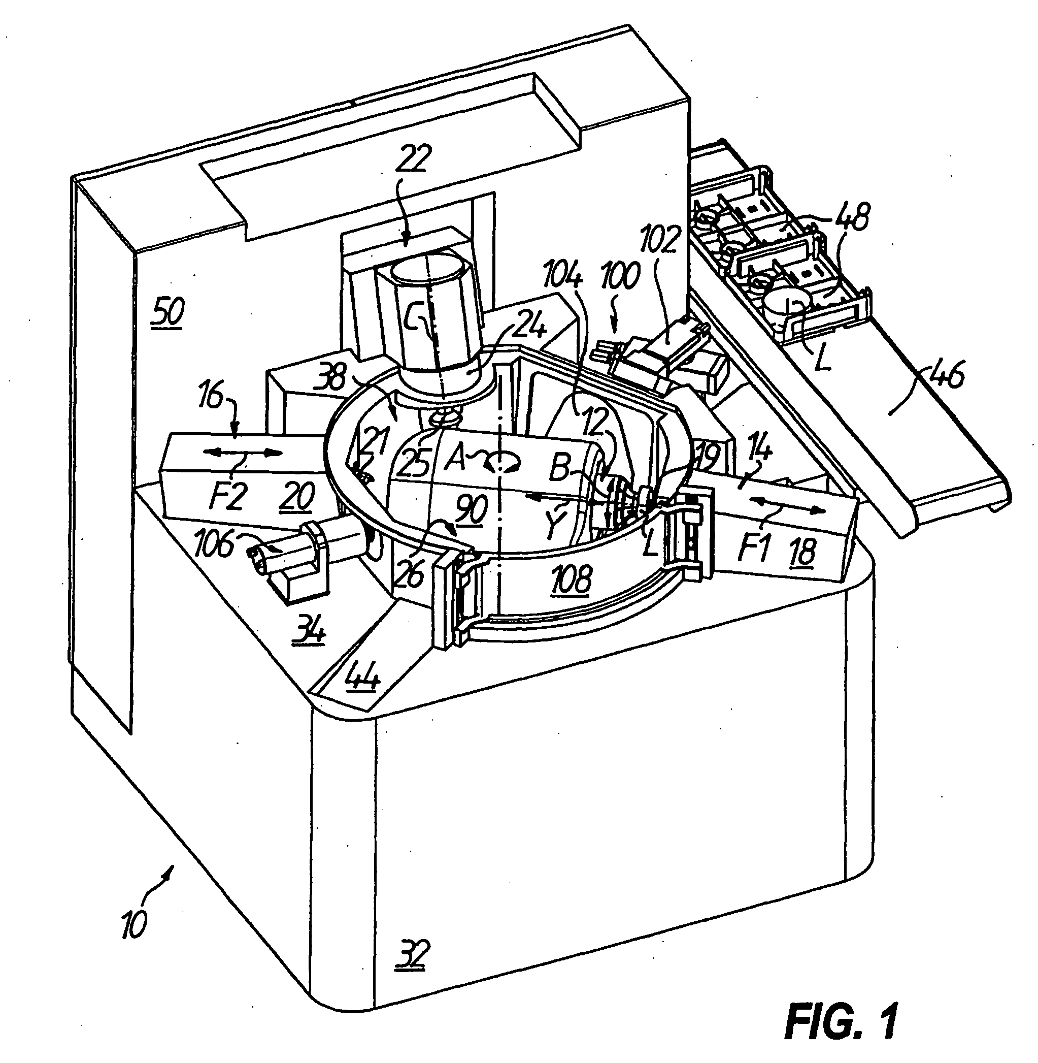
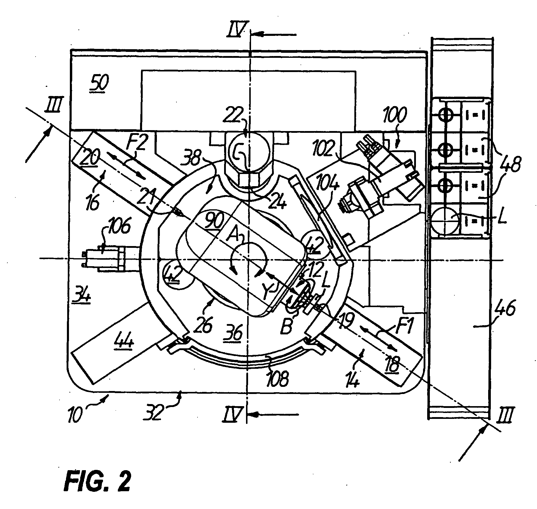
[0038]In FIGS. 1 to 4, 7, 9 and 10 a CNC-controlled machine in particular for processing the surface of plastic spectacle lenses L in indicated with 10. The machine 10 has in general[0039](a) a work piece spindle 12 by means of which the spectacle lens L can be driven rotationally about a work piece rotation axis B,[0040](b) at least one, in the example of embodiment shown even three processing units for machining the spectacle lens L that is retained on the work piece spindle 12, namely two lathe units 14, 16 each comprising a fast-tool arrangement 18, 20 for causing a linear movement in the direction F1 or F2 of a lathe tool 19, 21 respectively assigned as the tool, as well as a milling unit 22 with a tool spindle 24 for causing a rotational movement of a milling tool 25 about a tool rotation axis C, and[0041](c) an adjusting mechanism indicated in general with 26 for causing a relative movement between the work piece spindle 12 and the respective tool 19, 21, 25 in order to (at l...


PUM

PropertyMeasurementUnit
Angleaaaaaaaaaa
Circumferenceaaaaaaaaaa

Abstract

A machine for processing optical work pieces having a work piece spindle for the work piece driving rotationally about a work piece rotation axis. At least one processing unit has a tool that can machine the work piece and an adjusting mechanism causes a relative movement between the work piece spindle and tool to selectively enable loading, unloading and processing of the work piece. The adjusting mechanism has a linear drive unit and a swivel drive unit that are stacked on each other to rotate the swivel drive unit and the work piece spindle about a swivel axis that is perpendicular to the work piece rotation axis, and has the linear drive unit move the work piece spindle along a linear axis that can be perpendicular to one of the swivel axis and the work piece rotation axis and parallel to or aligned with the other axis.

Description

TECHNICAL FIELD[0001]The present invention relates to a machine for the processing of optical work pieces and in particular to the industrial manufacture of prescription surfaces of spectacle lenses made of plastic materials such as polycarbonate, CR39 and so called “High Index” materials.BACKGROUND OF THE DISCLOSURE[0002]Typically, in the manufacturing of plastic spectacle lenses, a spectacle lens blank produced by injection molding of plastic, also known as a “blank”, is used, that has a standardized finished outer surface with a convex shape, for example a spherical or progressive shape. The outer shape in conjunction with the usually concave inner or prescription surfaces produce a desired optical effect by attaining a machined spherical, aspherical, torical, atorical, progressive or freeform geometry (e.g. varifocal lenses). After blocking the spectacle lens blank with its outer surface onto a block piece, the typical conventional procedure for the processing of the inner surfa...

Claims


Application Information

Patent Timeline
IPC IPC(8): B24B5/00
CPCB24B13/0031B24B13/06Y10S29/086Y10T29/5129Y10T29/5128Y10T409/305824Y10T409/305264Y10T409/30392Y10T409/305432Y10T82/2514Y10T82/2566Y10T409/305768Y10T82/2524
Inventor SCHAFER, HOLGERWALLENDORF, STEFFEN
Owner SATISLOH AG
Why Eureka
Try Eureka