
Communication system for pipeline inspection

a communication system and pipeline technology, applied in the direction of measuring devices, instruments, structural/machine measurement, etc., can solve the problems of all pigs creating noise and vibration, damage to the system, and expensive shutdown, so as to improve the baselining process

Active Publication Date: 2009-01-15
QUANTA ASSOC
View PDF11 Cites 101 Cited by
  • Summary
  • Abstract
  • Description
  • Claims
  • Application Information

AI Technical Summary

Benefits of technology

[0009]The present invention provides a tracking and monitoring system for tracking and / or monitoring a pipeline inspection tool or pig as it moves through a pipe or conduit of a pipeline or the like. The monitoring system consists of the following components: (i) a tracking team or teams (including field team members and team members monitoring the pigging operation via the internet such as a central monitoring station personnel, pipeline operators, pump operators, supervisors or managers); (ii) a pig detection device capable of detecting the pig as it passes through the pipeline; (iii) a means to monitor the pig detection device, (iv) a communications network to allow the tracking team, or teams, and the pipeline operator to monitor the pig's progress as well as team locations, regardless of geographic position; (v) a system for correlating and adjusting or scaling the logged data to match the actual distance inspected by the pig; and (vi) a method for synchronizing the clocks in the system to improve the baselining process.
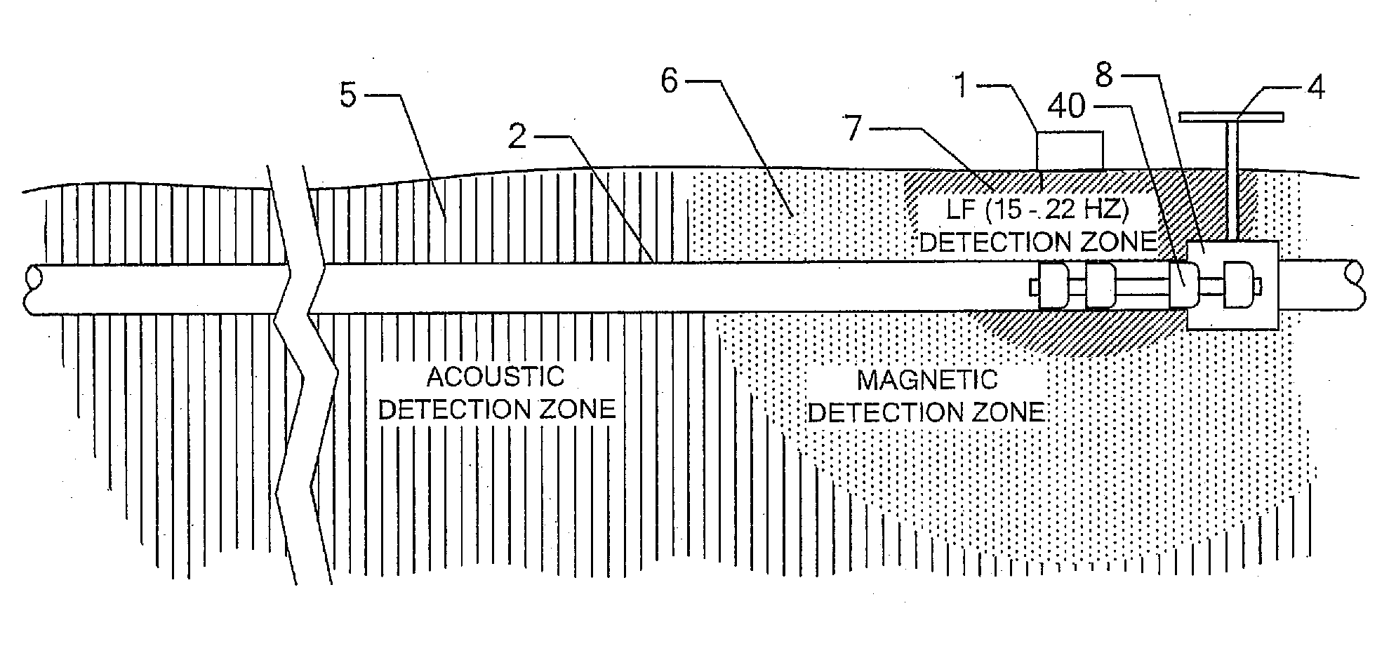
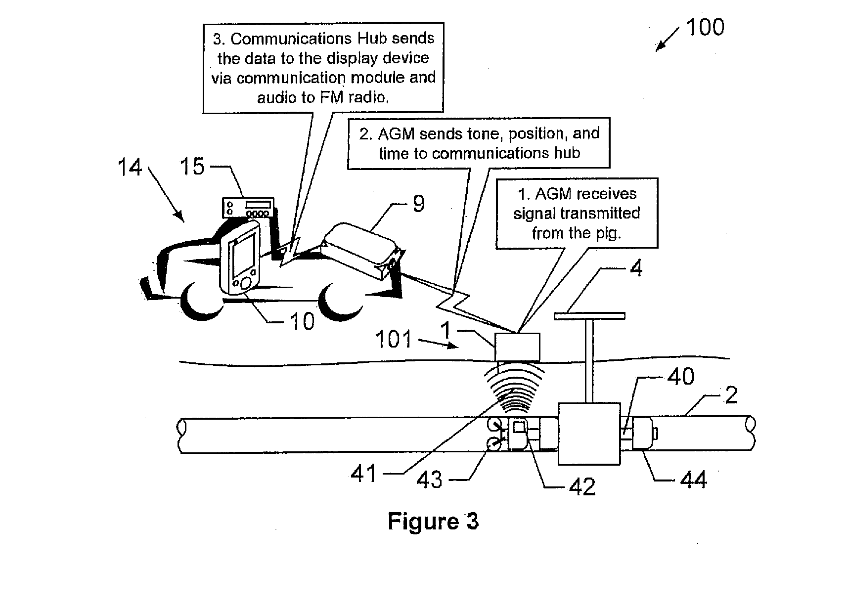
[0010]The tracking system of the present invention uses multiple detection methods to detect the approach and passage of the inline inspection (ILI) tool or tools (commonly referred to as “pigs”) as the tool progresses along and through the pipeline. The tracking system reports tool passage to both the tracking crew at the inspection point or data collection point or location or hub or above ground marker (AGM) and a central monitoring system, such as a remote server or control. The server, in turn, communicates the data to other tracking teams in the field to enable the entire team to monitor the progress of the tool and to see the locations of other team members while tracking the tool. Data collected at the passage event or AGM is stored at the AGM and at the Internet server to be used as a reference for correcting the time and position information gathered by the inspection tool. The communications hub enables the tracking crew to (i) monitor the status of the AGM and its sensory data; (ii) communicate with other tracking crews regardless of geographic separation; and / or (iii) monitor the location of an inspection tool as it passes other AGMs.
[0014]The detection and communication device may detect the inline tool via at least one of an acoustic detection device, a magnetic detection device and an electromagnetic frequency detection device, such as a low frequency detection device. Optionally, and desirably, the detection and communication device may detect the inline tool via an acoustic detection device, a magnetic detection device and an electromagnetic detection device. The control may receive geographical location data of the tracking communication devices from the tracking communication devices, whereby the control output may include the geographical location of the tracking communication devices, so that the team members in the field may readily determine or be alerted to which tracking vehicle is closest to the detected pig.
[0016]Therefore, the present invention provides a tracking system for tracking an inline inspection tool or pig as the pig travels along and through a pipeline. The tracking system provides enhanced detection capabilities and enhanced communication of the approach and arrival and passage of the tool or pig at particular passage points along the pipeline, such as via satellite communications. The tracking system communicates the pig detection data to tracking vehicles in the field so multiple vehicles or team members are notified of the pig passage to track and monitor the pig as it travels along and through the pipeline. The tracking system may also communicate the pig detection data to a central monitoring station via a satellite network. The enhanced detection capabilities and / or enhanced communication capabilities of the present invention may also allow the tracking system to more accurately and precisely locate a stationary and / or moving pig in the pipeline.

Problems solved by technology

A lost pig could damage the system or cause an expensive shutdown.
This often requires coordination between multiple teams located miles apart.
Also, virtually all pigs create noise and vibrations as they move through the pipe.
However, each of these detection methods has shortcomings and no method is always reliable.
Further, none of these detection methods is suitable for all pigs because different pigs have different characteristics.
Different soil conditions may also hinder or interfere with one or more detections methods.
Electrical transmission lines can also severely hinder low frequency detection and highway noises can obscure noises normally detected with a geophone.
However, using multiple devices increases the complexity and cost to the system and also increases the workload for the pigging crew.
In some cases, pigging crews have relied on a single AGM and mistakenly deployed the wrong type of AGM and failed to detect the pig as it went by.
However, odometers sometimes slip, or accumulate pipeline deposits on the odometer wheel, thus changing the diameter of the odometer wheel and thus leading to inaccurate measurements.
These problems can be the source of significant cumulative error over long distances.

Method used


Image

  • Communication system for pipeline inspection
  • Communication system for pipeline inspection
  • Communication system for pipeline inspection

Examples


Embodiment Construction

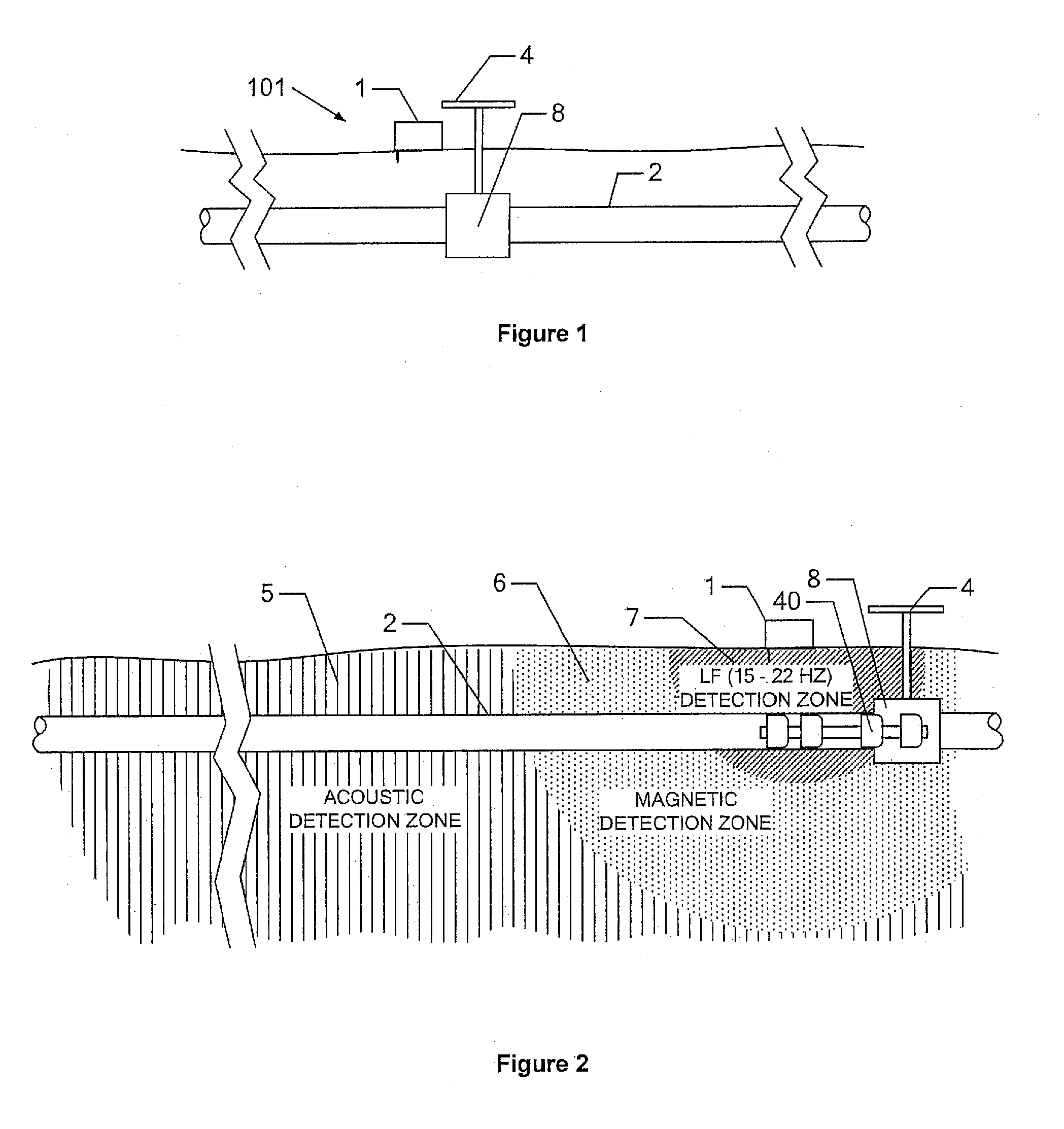
[0027]Referring now to the drawings and the illustrative embodiments depicted therein, a pipeline inspection tool tracking system or pig tracking system 100 is operable to track and / or monitor the approach of or location of a pipeline inspection tool or pig 40 as the pig travels along the pipeline. As used herein, the term “pig” is meant to encompass all types of pipeline pigs including inline inspection tools and the like. The system 100 is operable to track the geographic location of the pig 40 and may communicate the pig's location information and / or collected data or information to one or more tracking personnel, as discussed below. The system 100 is designed to detect the passage of the pig 40, notify the interested parties when the pig passes under an above ground reference (AGR) 4, and facilitate the movements of tracking personnel, as also discussed below.

[0028]As shown in FIGS. 1-4, system 100 includes an AGM system or detection system 101, which includes the above ground m...


PUM


Abstract

An inline tool tracking system for tracking an inline tool traveling along a pipe includes a detection and communication device operable to detect an inline tool as it passes generally near the device. The detection and communication device is operable to generate a detection output, which includes data indicative of the detection of the tool and a geographical location of the device. A control is operable to wirelessly receive the detection output and to process the detection output. The control generates a control output responsive to the processing, and the control output is indicative of the detection of the tool and the geographical location of the detection and communication device. A display device receives an input indicative of the control output and displays the information indicative of the detection of the tool and the geographical location of the detection and communication device to a user of the display device.

Description

CROSS REFERENCE TO RELATED APPLICATION[0001]The present application claims the benefit of U.S. provisional application Ser. No. 60 / 948,601, filed Jul. 9, 2007, which is hereby incorporated herein by reference in its entirety.BACKGROUND OF THE INVENTION[0002]Inline pipeline inspection involves sending an inspection tool through a pipe, typically while the pipe is carrying product. The inspection tools are commonly referred to as “pigs” and the process of sending a pig through a pipe is known in the industry as “pigging”. The pigs often travel through the pipeline for long distances, perhaps several hundred miles, and are propelled by the movement of the product (either liquid or gas) in the pipeline. Typically, to provide the motive force to move the pig, polyurethane sealing cups, or disks, are integrated into the pig's construction. The cups may completely seal or semi-seal at or against the inner wall of the pipe, creating a pressure differential that powers or propels the pig thr...

Claims


Application Information

Patent Timeline
Patent Type & Authority Applications(United States)
IPC IPC(8): G01M19/00G01M99/00
CPCF16L55/48
Inventor MILLER, JERRY E.PERRIN, RANDALL L.ANDERSON, JAMES D.REINHOLD, JABIN D.SPENCER, DOUGLAS W.
Owner QUANTA ASSOC
Learn More