Fuel vapor storage canister, fuel vapor adsorbent for canister, and method of producing fuel vapor adsorbent

a technology of adsorption and adsorption, which is applied in the direction of combustion air/fuel air treatment, machines/engines, mechanical equipment, etc., can solve the problems of not improving the adsorption and desorption performance to expected levels, the flow resistance (pressure drop) of the canister can be lowered, and the speed of adsorption and desorption of fuel vapor to activated carbon is lowered, so as to improve the adsorption and desorption performance. performan

Active Publication Date: 2009-01-15
MAHLE JAPAN LTD
View PDF6 Cites 39 Cited by
  • Summary
  • Abstract
  • Description
  • Claims
  • Application Information

AI Technical Summary

Benefits of technology

[0007]Furthermore in the above conventional techniques, for example, in case that the particle diameter of activated carbon located near the atmospheric air port is positively increased, a flow resistance (pressure drop) of the canister can be lowered; however, the speed of adsorption and desorption of fuel vapor to activated carbon is lowered with such an increase in particle diameter of activated carbon, thereby not necessarily improving the adsorbing and desorbing performances to expected levels.
[0008]In view of the above, an object of the present invention is to provide improved fuel vapor storage canister, fuel vapor adsorbent and production method for the fuel vapor adsorbent, which can overcome drawbacks encountered in the above conventional techniques.
[0009]Another object of the present invention is to provide improved fuel vapor storage canister, fuel vapor adsorbent and production method for the fuel vapor adsorbent, which makes it possible to sufficiently restrain fuel vapor from leaking through an atmospheric air port through which atmospheric air is introduced into the canister.
[0010]A further object of the present invention is to provide improved fuel vapor storage canister, fuel vapor adsorbent and production method for the fuel vapor adsorbent, which makes it possible to improve fuel vapor adsorbing and desorbing performances of the canister over conventional fuel vapor storage canisters.

Problems solved by technology

In the conventional techniques as disclosed in the above Patent Publications, the particle diameter and / or the pore diameter of activated carbon filled in the casing of the canister are positively changed according to the positions in flow direction of fuel vapor; however, a premise is such that the cross-sectional area of the inside of the casing itself, i.e., passage area for fuel vapor in the canister is basically constant, and therefore fuel vapor cannot be sufficiently restrained from leaking through the atmospheric air port since the atmospheric air port is opened to the atmospheric air.
Furthermore in the above conventional techniques, for example, in case that the particle diameter of activated carbon located near the atmospheric air port is positively increased, a flow resistance (pressure drop) of the canister can be lowered; however, the speed of adsorption and desorption of fuel vapor to activated carbon is lowered with such an increase in particle diameter of activated carbon, thereby not necessarily improving the adsorbing and desorbing performances to expected levels.

Method used


Image

  • Fuel vapor storage canister, fuel vapor adsorbent for canister, and method of producing fuel vapor adsorbent
  • Fuel vapor storage canister, fuel vapor adsorbent for canister, and method of producing fuel vapor adsorbent
  • Fuel vapor storage canister, fuel vapor adsorbent for canister, and method of producing fuel vapor adsorbent

Examples


Embodiment Construction

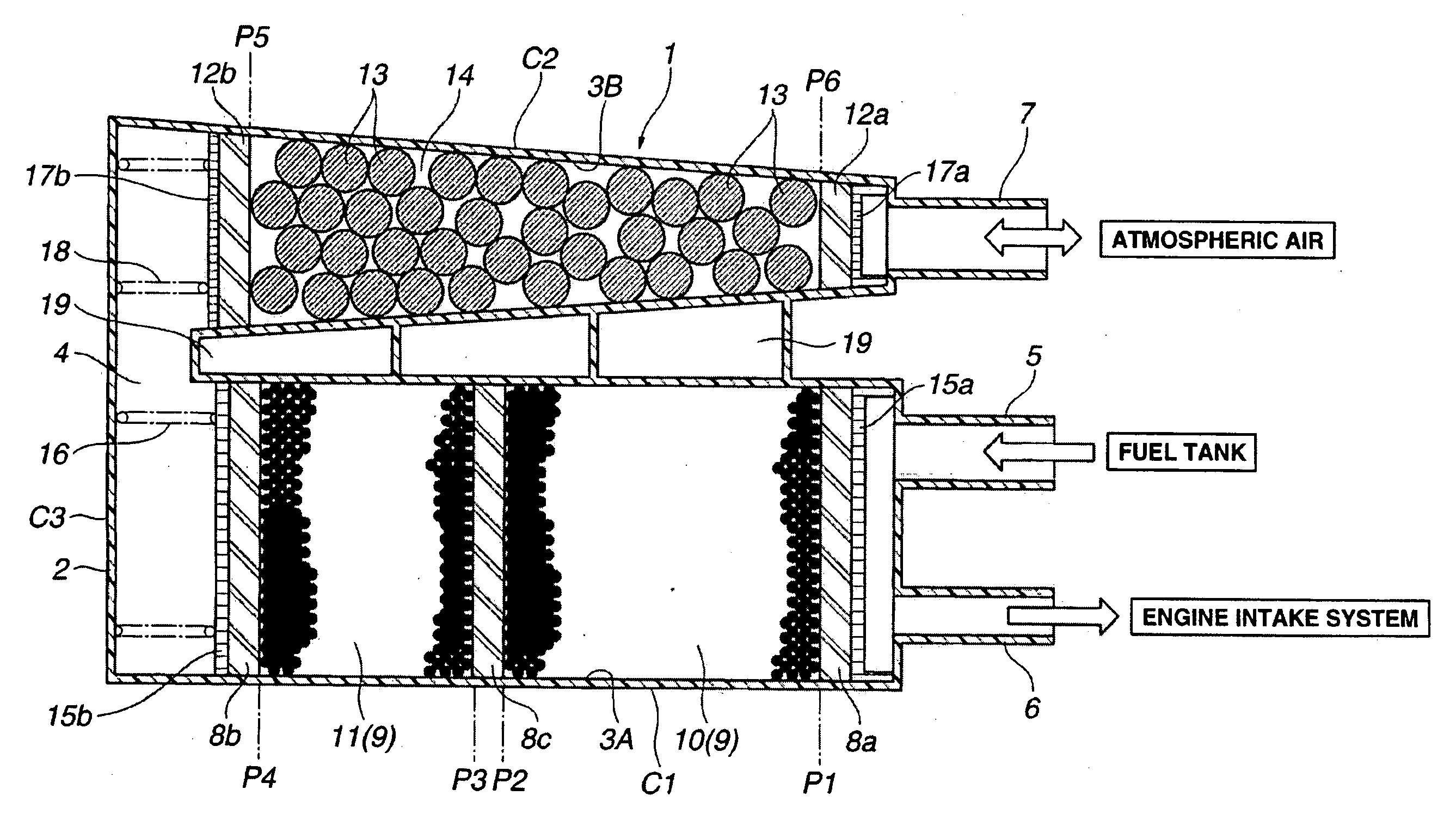
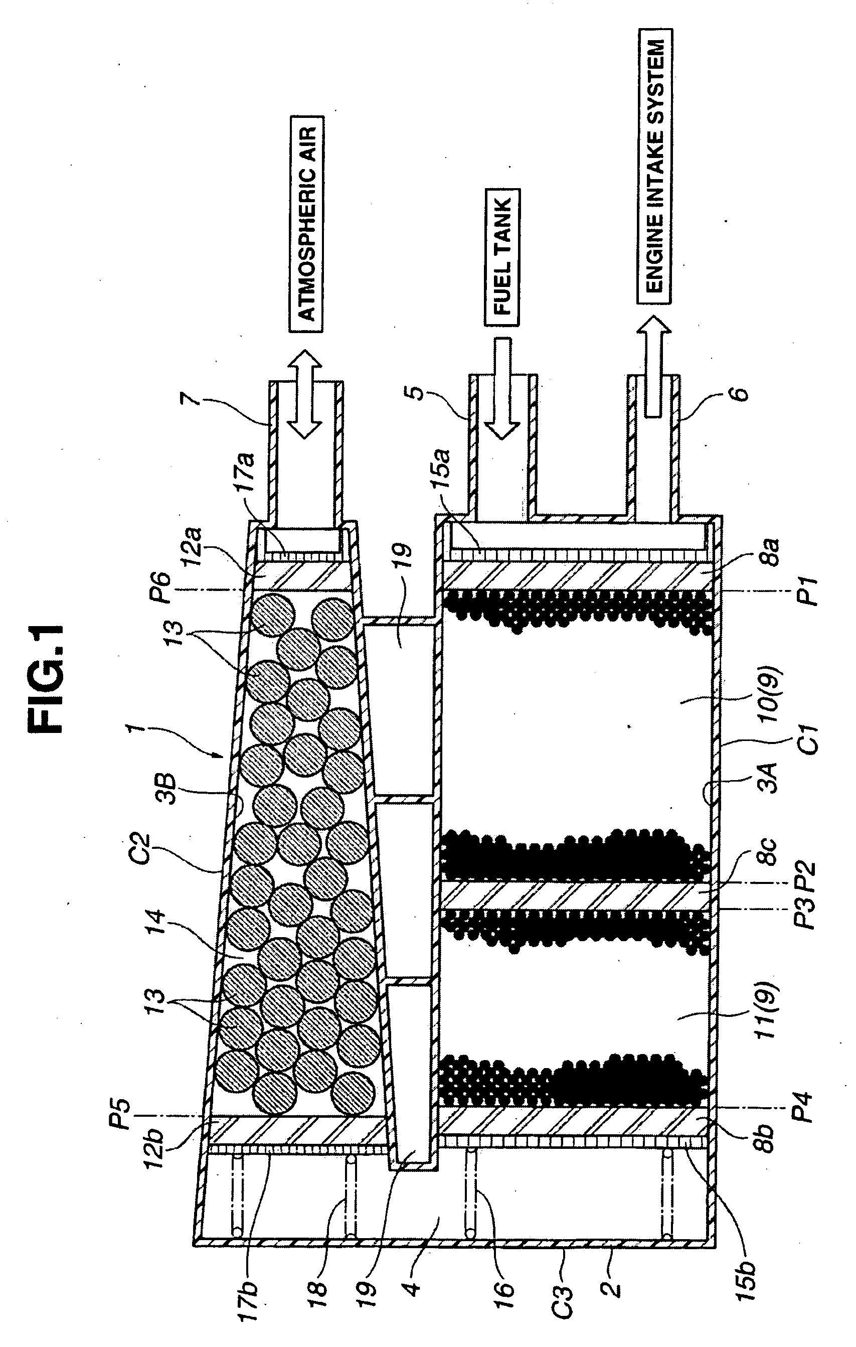
[0019]Referring now to FIG. 1 of the drawings, a first embodiment of a closed-type fuel vapor storage canister 1 according to the present invention is illustrated. The fuel vapor storage canister 1 of this embodiment is mounted on an automotive vehicle provided with an internal combustion engine. The canister 1 is of a so-called two-chamber and U-turn flow structure and comprises a casing 2 as a main body, formed of a resin material or plastic such as polyamide resin. The casing 2 includes first and second cylindrical sections C1. C2 which respectively define thereinside main and auxiliary chambers 3A, 3B which are separate from each other. The main chamber 3A is larger in volume than the auxiliary chamber 3B. The maim chamber 3A is, for example, prism-shaped, and the auxiliary chamber 3B is, for example, of the shape of a frustum of pyramid so as to be tapered in cross-section along its length. The main and auxiliary chambers 3A, 3B are in communication with each other through a co...


PUM


Abstract

A fuel vapor storage canister for adsorbing fuel vapor evaporated from a fuel tank of an automotive vehicle. The fuel vapor storage canister includes a casing provided with charge and purge ports at its first end and an atmospheric port at its second end. At least first and second fuel vapor adsorbent layers are respectively located near the first and second ends of the casing. In this arrangement, the first fuel vapor adsorbent layer is larger in cross-sectional area perpendicular to flow direction of fuel vapor than the second fuel vapor adsorbent layer. The first and second fuel vapor adsorbent layers respectively include first and second granular fuel vapor adsorbents. The first granular fuel vapor adsorbent has a microporous structure, while the second granular fuel vapor adsorbent has a macroporous structure.

Description

BACKGROUND OF THE INVENTION[0001]This invention relates to improvements in a fuel vapor storage canister serving as a fuel vapor treatment device for adsorbing fuel evaporated, for example, in a fuel tank of an automotive vehicle in order to combust the fuel in an engine during operation of the engine, fuel vapor adsorbent used in the fuel vapor storage canister, and a method of producing the fuel vapor adsorbent.[0002]As is well known, a fuel vapor storage canister has been generally used as a fuel vapor treatment device in order to suppress release of fuel vapor generated within a fuel tank to atmospheric air in a gasoline-fueled automotive vehicle. This canister includes a casing formed thereinside a gas passage which is filled with a fuel vapor adsorbent such as activated carbon. Charge and purge ports for fuel vapor are communicated with one end of the gas passage, while an atmospheric port (drain port) for fuel vapor is communicated with the other end of the gas passage, thus ...

Claims


Application Information

Patent Timeline
Patent Type & Authority Applications(United States)
IPC IPC(8): F02M33/02
CPCF02M25/0854B01D2259/4516
Inventor YAMASAKI, KOJI
Owner MAHLE JAPAN LTD
Why Eureka
Try Eureka