Components capable of transporting liquids manufactured using injection molding

a technology of components and liquids, which is applied in the direction of mechanical equipment, machines/engines, lighting and heating apparatus, etc., can solve the problems of increasing the time needed to fabricate such components, and affecting the quality of components

Inactive Publication Date: 2009-01-15
GENERAL ELECTRIC CO
View PDF15 Cites 17 Cited by
  • Summary
  • Abstract
  • Description
  • Claims
  • Application Information

AI Technical Summary

Problems solved by technology

It is therefore important that the fuel supply and distribution systems are substantially leak free, as a leak in the fuel supply or distribution systems could be catastrophic.
Due largely to the number of braze joints required to construct fuel nozzles in this manner, the use of macro-laminate technology is not ideal.
More specifically, the use of braze joints can increase the time needed to fabricate such components and can also complicate the fabrication process for any of several reasons, including: the need for an adequate regio

Method used


Image

  • Components capable of transporting liquids manufactured using injection molding
  • Components capable of transporting liquids manufactured using injection molding
  • Components capable of transporting liquids manufactured using injection molding

Examples


Embodiment Construction

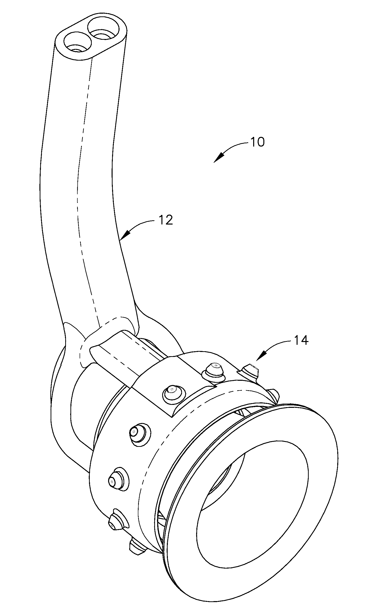
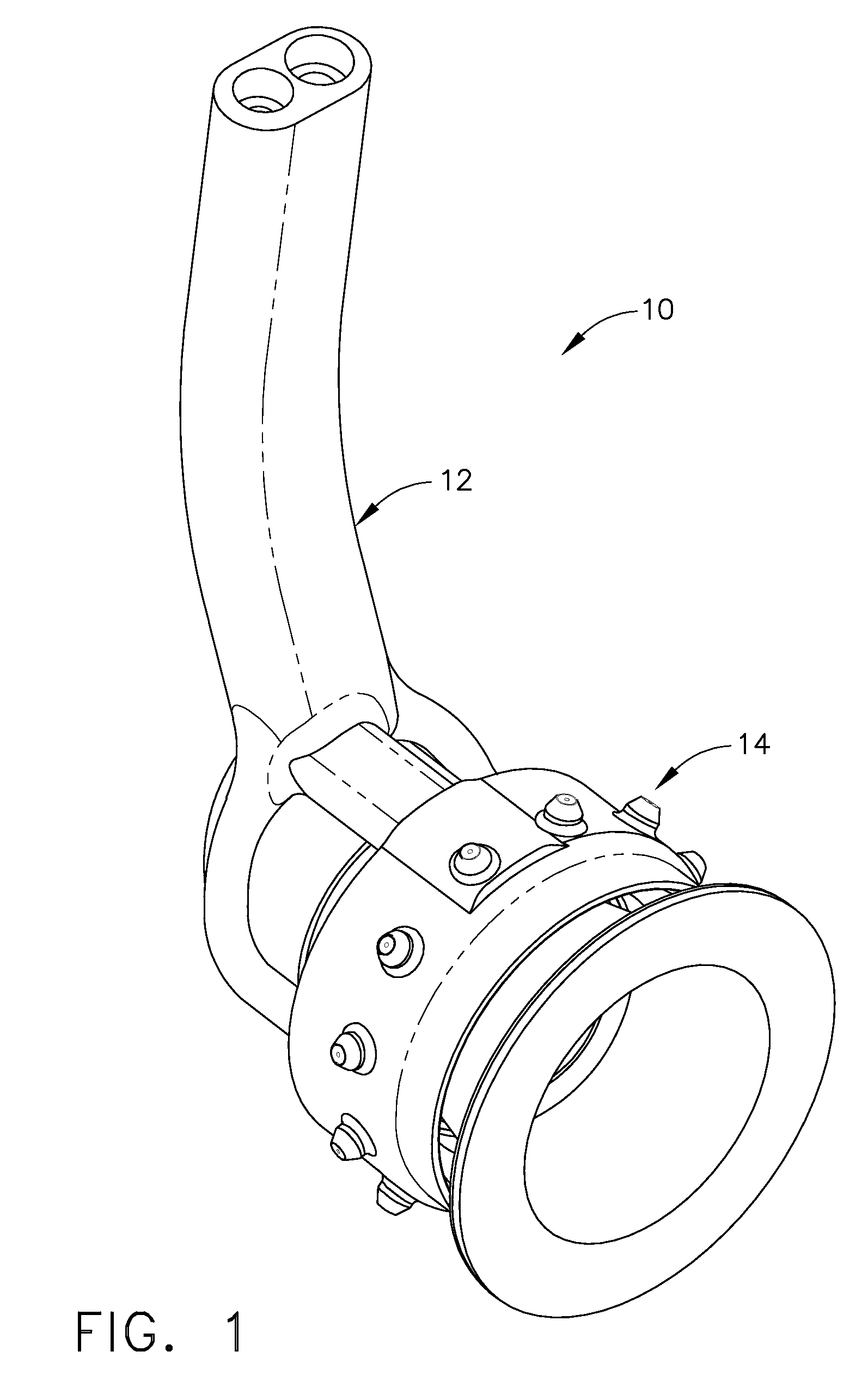
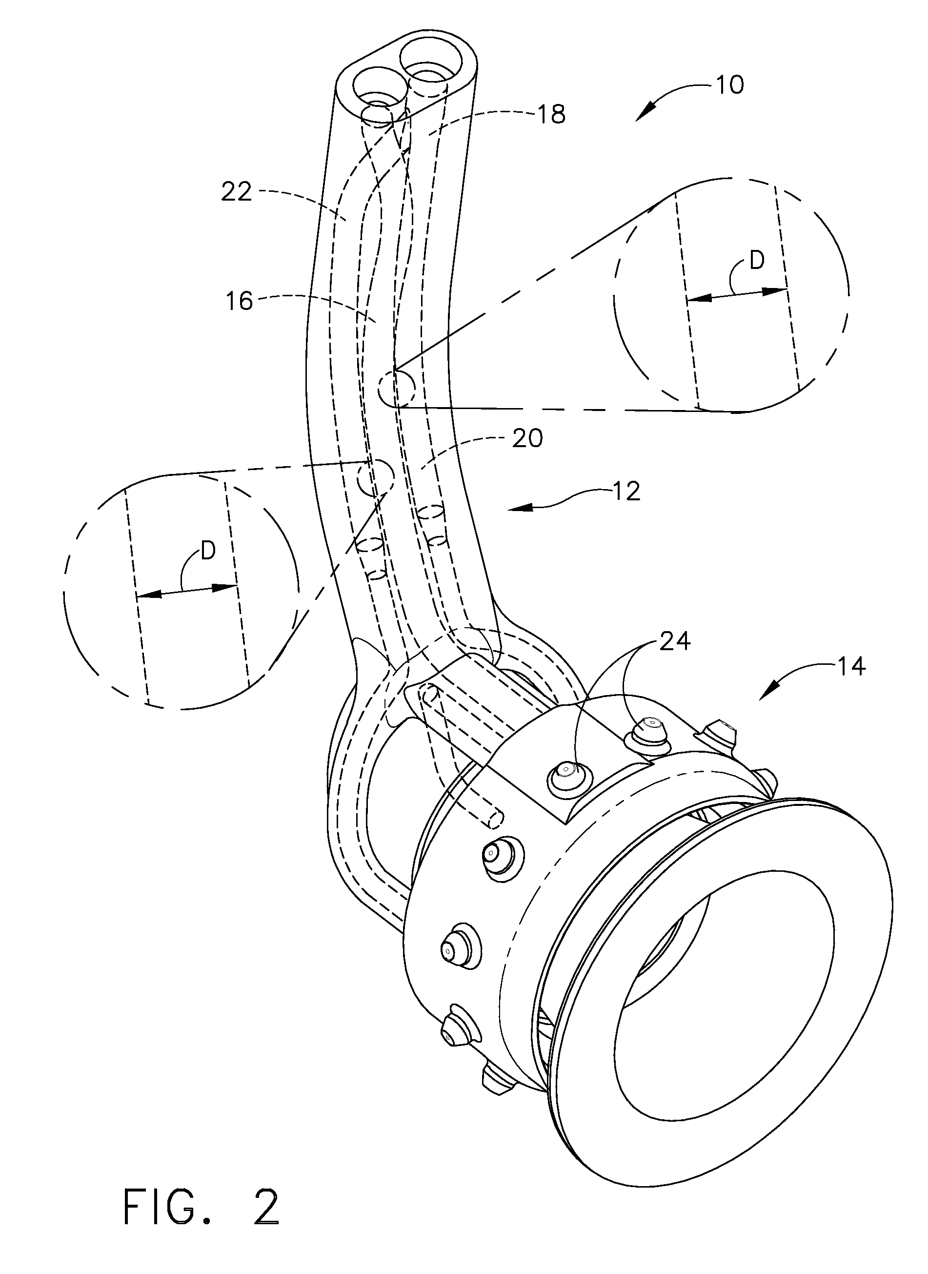
[0017]Embodiments described herein generally relate to components capable of transporting liquids manufactured using metal injection molding methods. While embodiments herein may generally focus on components useful in the transport of jet fuel through the fuel systems of gas turbine engines, it will be understood by those skilled in the art that the description should not be limited to such. Indeed, as the following description explains, the methods described herein may be utilized to produce any component capable of being used to transport a liquid.

[0018]Generally, embodiments set forth herein relate to providing a mold, injecting a component material into the mold to produce a green component, heating the green component to produce a brown component, and sintering the brown component to produce a finished component capable of transporting a liquid.

[0019]Initially, a mold may be provided having the form of the desired finished component. The mold may be any mold suitable for use w...


PUM

PropertyMeasurementUnit
Lengthaaaaaaaaaa
Distanceaaaaaaaaaa

Abstract

Fuel nozzles including a fuel conduit supply having at least one pilot cavity and at least one main cavity, and a distributor ring having at least one injection post extending outwardly therefrom, the distributor ring operably coupled to each of the at least one pilot cavity and at least one main cavity wherein the nozzle is fabricated using metal injection molding.

Description

TECHNICAL FIELD[0001]Embodiments described herein generally relate to components capable of transporting liquids manufactured using metal injection molding methods. More specifically, embodiments described herein relate generally to fuel nozzles manufactured using metal injection molding.BACKGROUND OF THE INVENTION[0002]In gas turbine engines, such as aircraft engines, air is drawn into the front of the engine and then compressed by a shaft-mounted compressor. The compressed air is then transported to the combustor while fuel is concurrently transported from a fuel supply by a fuel distribution system to the combustor. More specifically, the fuel is introduced at the front end of a burner in a highly atomized spray from a fuel nozzle. Compressed air flows in around the fuel nozzle and mixes with the fuel to form a fuel-air mixture, which is ignited by the burner. The temperature of the ignited fuel-air mixture can reach an excess of 3500° F. (1920° C.). It is therefore important tha...

Claims


Application Information

Patent Timeline
IPC IPC(8): F02M61/00
CPCB22F3/225B22F5/106B22F7/062B22F2998/10F23D2212/00F23D2213/00F23R3/14Y02T50/675F23R3/343B22F3/1021B22F3/15Y02T50/60
Inventor MCMASTERS, MARIE ANNBUDINGER, DAVID EDWINDURSTOCK, DANIEL L.
Owner GENERAL ELECTRIC CO
Why Eureka
Try Eureka