Light emitting apparatus with open loop control

a technology of light emitting apparatus and control circuit, which is applied in the direction of discharge tube/lamp details, discharge tube/solid-state device details, discharge tube luminescnet screens, etc., can solve the problems of increasing manufacturing costs, inability to automatically compensate, and complicated control circuits for the first and second methods

Inactive Publication Date: 2009-01-15
LITE ON TECH CORP
View PDF14 Cites 62 Cited by
  • Summary
  • Abstract
  • Description
  • Claims
  • Application Information

AI Technical Summary

Problems solved by technology

However, control circuits for the first and second methods are far more complicated and, hence, increase the manufacturing cost.
However, the chromaticity coordinate of the white beam generated by an LED and phosphor is related to the light beams from the LED and phosphor, and cannot be compensated automatically.
Thus, the white light beam cannot be made to have a constant chromaticity coordinate.

Method used


Image

  • Light emitting apparatus with open loop control
  • Light emitting apparatus with open loop control
  • Light emitting apparatus with open loop control

Examples


first embodiment

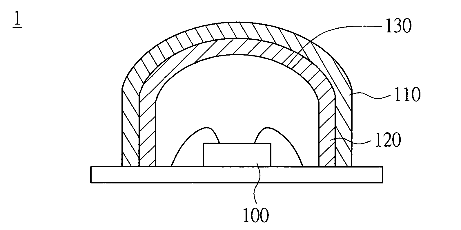
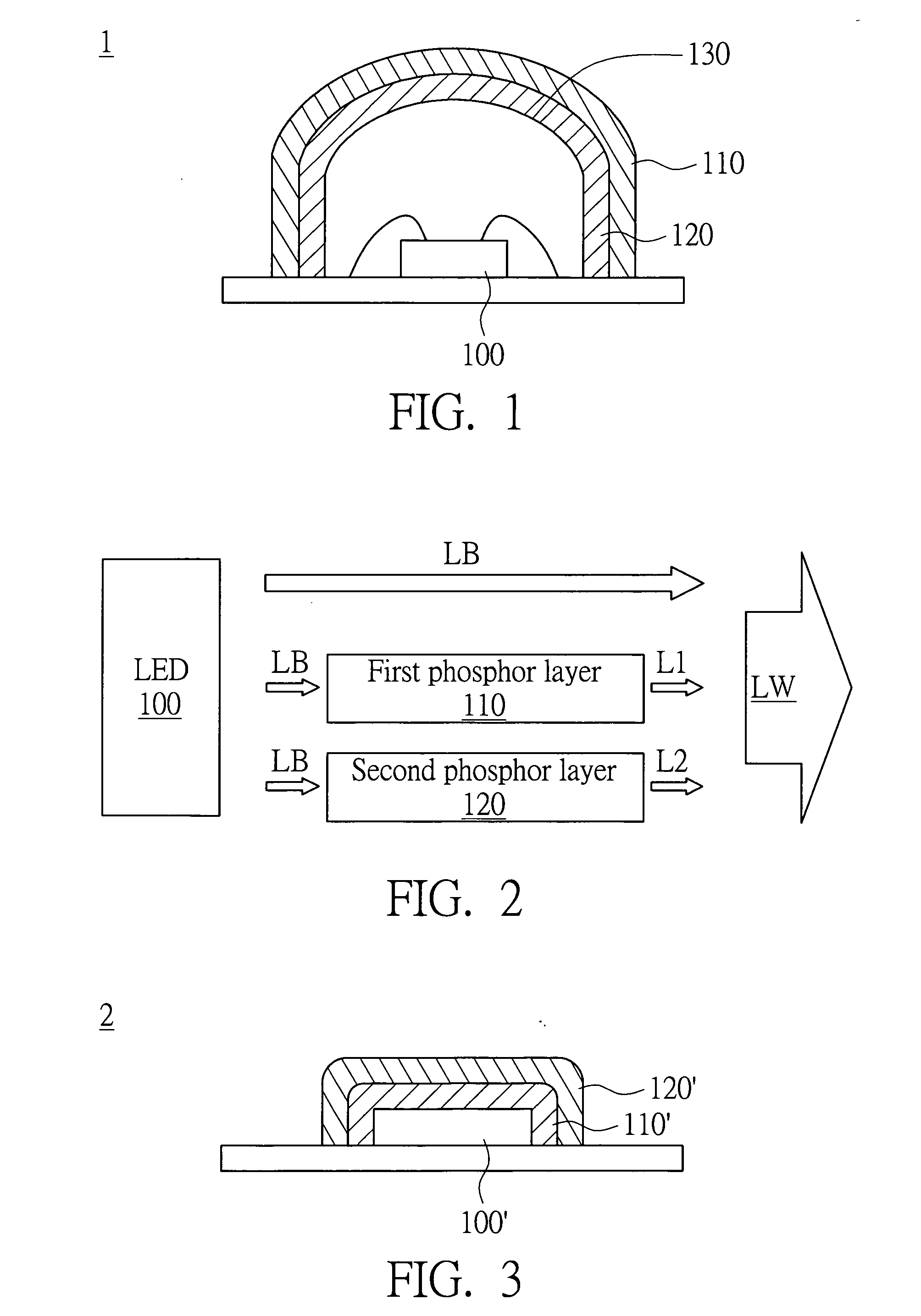
[0026]FIG. 1 is a diagram showing a light emitting apparatus according to a first embodiment of the invention, and FIG. 2 is a system diagram showing the chromaticity coordinate control of the light emitting apparatus in FIG. 1. The light emitting apparatus 1 includes a blue LED 100, a first phosphor layer 110 and a second phosphor layer 120. The first phosphor layer 110 is disposed above the blue LED 100 and has a first phosphor material that is excited by a blue beam LB from the blue LED 100. The second phosphor layer 120 is disposed between the blue LED 100 and the first phosphor layer 110, and has a second phosphor material that is also excited by the blue beam LB from the blue LED 100. When a blue beam of a shorter wavelength excites the first phosphor layer 110 and the second phosphor layer 120, the excitation efficiency of the first phosphor layer 110 is greater than that of the second phosphor layer 120. When a blue beam of a longer wavelength excites the first phosphor laye...

second embodiment

[0057]The light emitting apparatus in the second embodiment differs from that of the first embodiment in the location of the deposited phosphor layer. The materials of the blue LED and phosphors are the same as that of the first embodiment, as is the method of preparation for the phosphors. We do not repeat the explanation here.

[0058]FIG. 9 is a diagram showing a light emitting apparatus according to the second embodiment of the invention. The light emitting apparatus 2 includes a blue LED 200, a phosphor layer 205 and a transparent sealed body 230. The blue LED 200 is received within the transparent sealed body 230. The phosphor layer 205, which is a thin film, is formed over the transparent sealed body 230 by coating, and is separated from the blue LED 200. The phosphor layer 205 includes a first phosphor material and a second phosphor material that are excited by a blue beam from the blue LED 200.

[0059]The first and second phosphor materials of the phosphor layer 205 have the cha...


PUM


Abstract

A light emitting apparatus includes a blue light emitting diode (LED), a first and second phosphor layers. The second phosphor layer is between the blue LED and the first phosphor layer. When a blue beam of a shorter wavelength excites the phosphor layers, the excitation efficiency of the first phosphor layer is greater than that of the second phosphor layer. When a blue beam of a longer wavelength excites the phosphor layers, the excitation efficiency of the first phosphor layer is less than that of the second phosphor layer. Moreover, the wavelength of the peak intensity of the light beam from the first phosphor layer is shorter than that of the second phosphor layer. And, the dividing value between the shorter wavelength and the longer wavelength is within the range from a first wavelength to a second wavelength.

Description

[0001]This application claims the benefit of Taiwan application Serial No. 96125539, filed Jul. 13, 2007, the subject matter of which is incorporated herein by reference.BACKGROUND OF THE INVENTION[0002]1. Field of the Invention[0003]The invention relates in general to a light emitting apparatus, and more particularly to a light emitting apparatus with open loop control.[0004]2. Description of the Related Art[0005]Products that make use of light emitting diodes (LED) are, for example, backlights of liquid crystal display (LCD) devices, lighting devices for particular uses and vehicles, etc. In 2005, LEDs had a marketing value of 6.235 billion dollars worldwide. And in 2006, it had increased to 6.873 billion dollars. Therefore, it is anticipated that products utilizing LEDs will steadily increase in number and variety in the future. At present, white LEDs are commonly used as light sources for providing white light. A known method for fabricating a white LED is to integrate several l...

Claims


Application Information

Patent Timeline
Patent Type & Authority Applications(United States)
IPC IPC(8): H01J1/62
CPCH01L33/504H01J1/63
Inventor SU, HUNG-YUANLIU, RU-SHI
Owner LITE ON TECH CORP
Why Eureka
Try Eureka