Voltage generating apparatus

a voltage generation and voltage technology, applied in the field of voltage generation technology, can solve the problems of voltage variation, limited bandwidth of the feedback loop, and problems such as the voltage generation apparatus in the dc test equipment, and achieve the effect of reducing the risk of voltage generation, and reducing the efficiency of voltage generation

Inactive Publication Date: 2009-01-15
ADVANTEST CORP
View PDF4 Cites 16 Cited by
  • Summary
  • Abstract
  • Description
  • Claims
  • Application Information

AI Technical Summary

Benefits of technology

[0008]In this background, a general purpose of the present invention is to provide a voltage ge

Problems solved by technology

The bandwidth of the feedback loop is limited due to the bandwidth of an operational amplifier used in the voltage generating apparatus and a filter formed by the output impedance of the voltage generating apparatus and the output capacitor.
This will cause failure of the charging and discharging

Method used


Image

  • Voltage generating apparatus
  • Voltage generating apparatus
  • Voltage generating apparatus

Examples


first embodiment

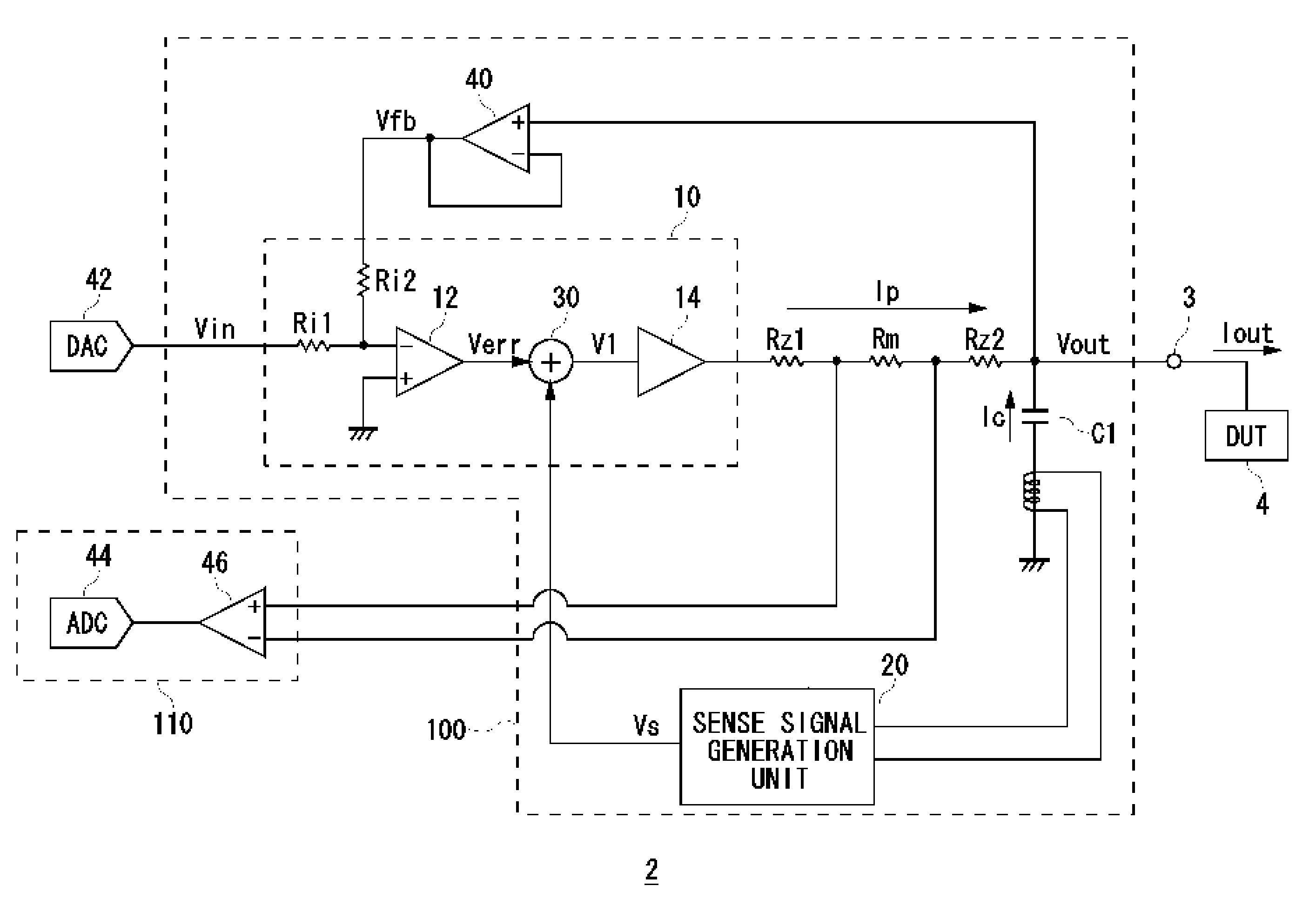
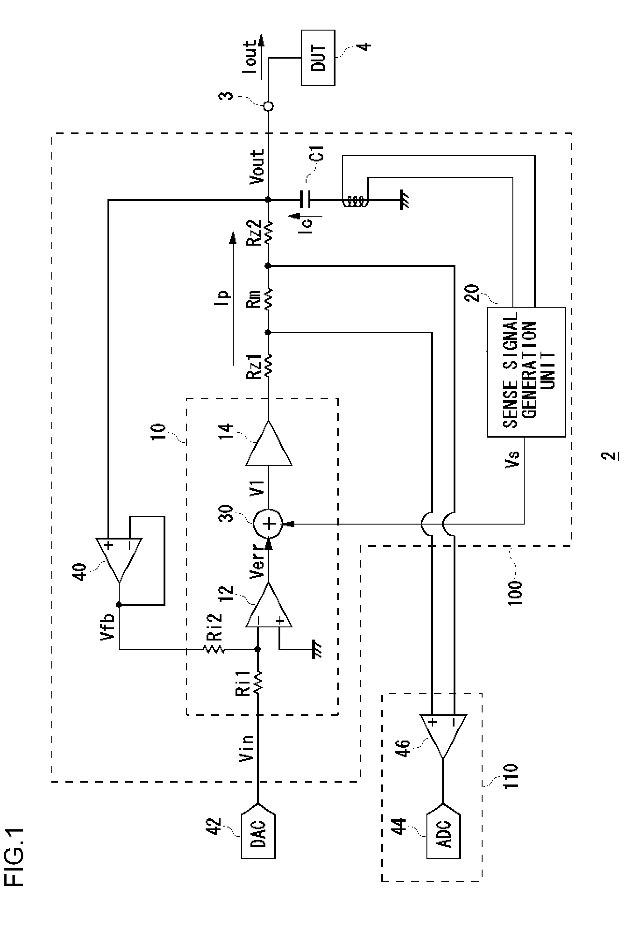
[0040]FIG. 1 is a circuit diagram of DC test equipment 2 according to the first embodiment. The DC test equipment 2 is provided with an output terminal 3 adapted to be connected to a DUT 4. The DC test equipment 2 outputs a DC voltage Vout to the DUT 4 via the output terminal 3 and monitors a current Iout flowing into the DUT 4 while the DC voltage Vout is being applied to the DUT 4.

[0041]The DC test equipment 2 includes a voltage generating apparatus 100, a voltage measuring unit 110, and a DA converter 42. The voltage generating apparatus 100 generates a stable DC voltage (hereinafter, also referred to as an output voltage) Vout. The DA converter 42 is fed a digital value configured by the user and converts the digital value into an analog voltage for output. The voltage generating apparatus 100 receives the output of the DA converter 42 as an input voltage Vin. The voltage generating apparatus 100 generates the output voltage Vout with reference to the input voltage Vin. The DC t...

second embodiment

[0081]In the first embodiment, a description is given of the superimposition of the sense signal Vs proportional to the capacitor current Ic on the output of the first operational amplifier 12. In contrast, a description will be given in the second embodiment of the superimposition of the sense signal Vs on the input to the first operational amplifier 12.

[0082]FIG. 7 is a circuit diagram showing the structure of a voltage generating apparatus 100c according to the second embodiment. Three adder-subtractor circuits 30c-30e of the voltage generating apparatus 100c represent points where the sense signal Vs may be superimposed. Only one of the circuits 30c-30e may be provided.

[0083](1) The adder-subtractor circuit 30c superimposes the sense signal Vs on the feedback voltage Vfb (Vout). In this case, the sense signal Vs is inverted before superimposition. By superimposing the inverted sense signal Vs on the feedback voltage Vfb, the first operational amplifier 12 determines that the out...


PUM


Abstract

A voltage generating apparatus generates an output voltage based on an input voltage. A voltage generator includes a first operational amplifier operative to receive the input voltage and a feedback voltage proportional to the output voltage. The voltage generator regulates the output voltage so that a virtual short circuit is produced in the first operational amplifier. An output capacitor smoothes the output voltage generated by the voltage generating apparatus. A sense signal generator detects a current flowing in the output capacitor and generates a sense signal proportional to the current detected. An adder-subtractor circuit superimposes the sense signal on at least one of the input and the output of the first operational amplifier.

Description

CLAIM OF PRIORITY[0001]This application claims foreign priority for Japanese application number JP2007-132586, filed May 18, 2007.BACKGROUND OF INVENTION[0002]1. Field of the Invention[0003]The present invention relates to a voltage generation technology for generating a stable voltage.[0004]2. Description of the Related Art[0005]DC test equipment is used to measure various characteristics of electronic circuits. DC test equipment is provided with the function of supplying a desired stable voltage to a terminal of a device under test (hereinafter, referred to as DUT) and monitoring a current flowing into the terminal. Generally, DC test equipment is provided with a digital-to-analog converter (hereinafter, referred to as a DA converter) for converting an input digital signal into an analog voltage, a voltage generating apparatus for generating a stable output voltage with reference to the analog voltage from the DA converter, and an analog-to-digital converter (hereinafter, referred...

Claims


Application Information

Patent Timeline
IPC IPC(8): G05F1/565
CPCG01R31/31924G01R31/2841
Inventor KODERA, SATOSHI
Owner ADVANTEST CORP
Why Eureka
Try Eureka