
Resonator-based magnetic field sensor

a magnetic field sensor and resonance frequency technology, applied in the direction of magnetic field magnitude/direction, measurement devices, instruments, etc., can solve the problems of important variation of sensitivity, deformation of excitation-oscillator tuning with the resonance frequency of the moving structure,

Inactive Publication Date: 2009-01-15
SENSIRION AG
View PDF1 Cites 28 Cited by
  • Summary
  • Abstract
  • Description
  • Claims
  • Application Information

AI Technical Summary

Benefits of technology

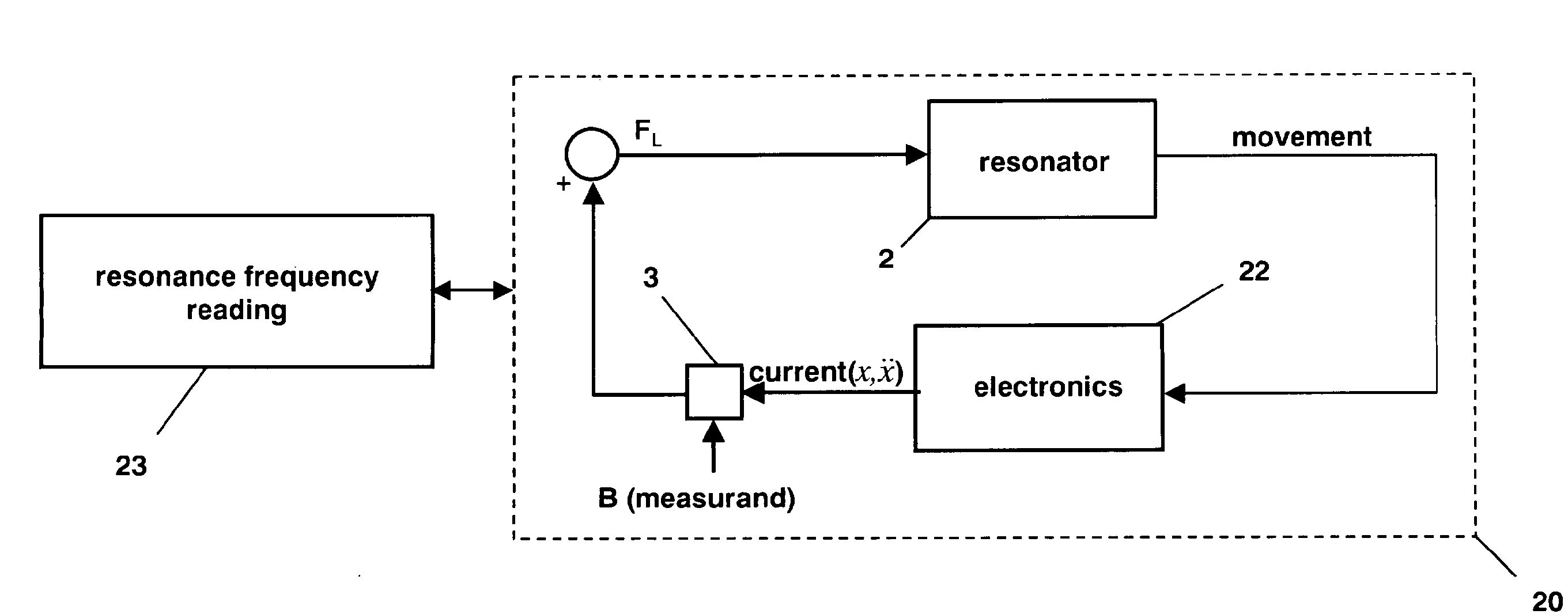
[0019]The method exploited in the preferred embodiment consists in using the measurand-altered resonator as the frequency-determining element of an electrical oscillator. In this architecture, the secondary excitation works in closed-loop (feed-back) and is used to start, sustain and stabilize the resonator oscillation. When the sensor is correctly tuned, it oscillates at the resonance frequency of the measurand-altered resonator and automatically tracks it. This results in the architecture illustrated in FIG. 3. Another advantage of this implementation is that the current generating the Lorentz force can be switched off while the secondary excitation loop is still active. This way, the resonance frequency of the resonator, which may change as a function of the environmental conditions or the aging of the device, can easily be measured without the measurand influence, even in the presence of the measurand. A continuous offset cancellation can thus be performed.

Problems solved by technology

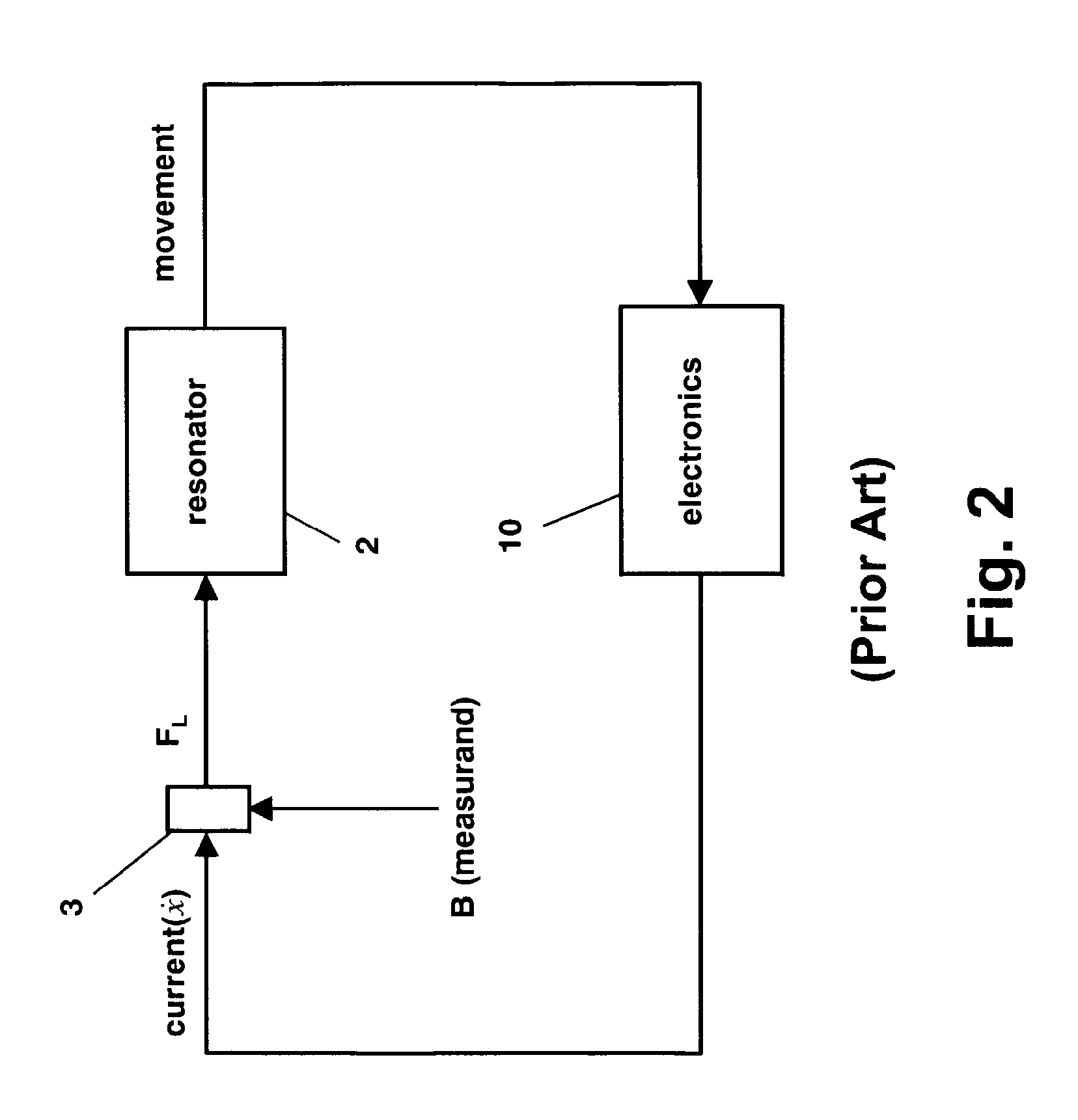
The drawback of open-loop-excitation approaches is that the matching of the excitation-oscillator tuning with the resonance frequency of the moving structure may degrade with aging or environmental condition changes, leading to important variation of sensitivity.

Method used


Image

  • Resonator-based magnetic field sensor
  • Resonator-based magnetic field sensor
  • Resonator-based magnetic field sensor

Examples


Embodiment Construction

[0020]The following is a detailed description of a preferred embodiment in connection with a number of drawings in which:

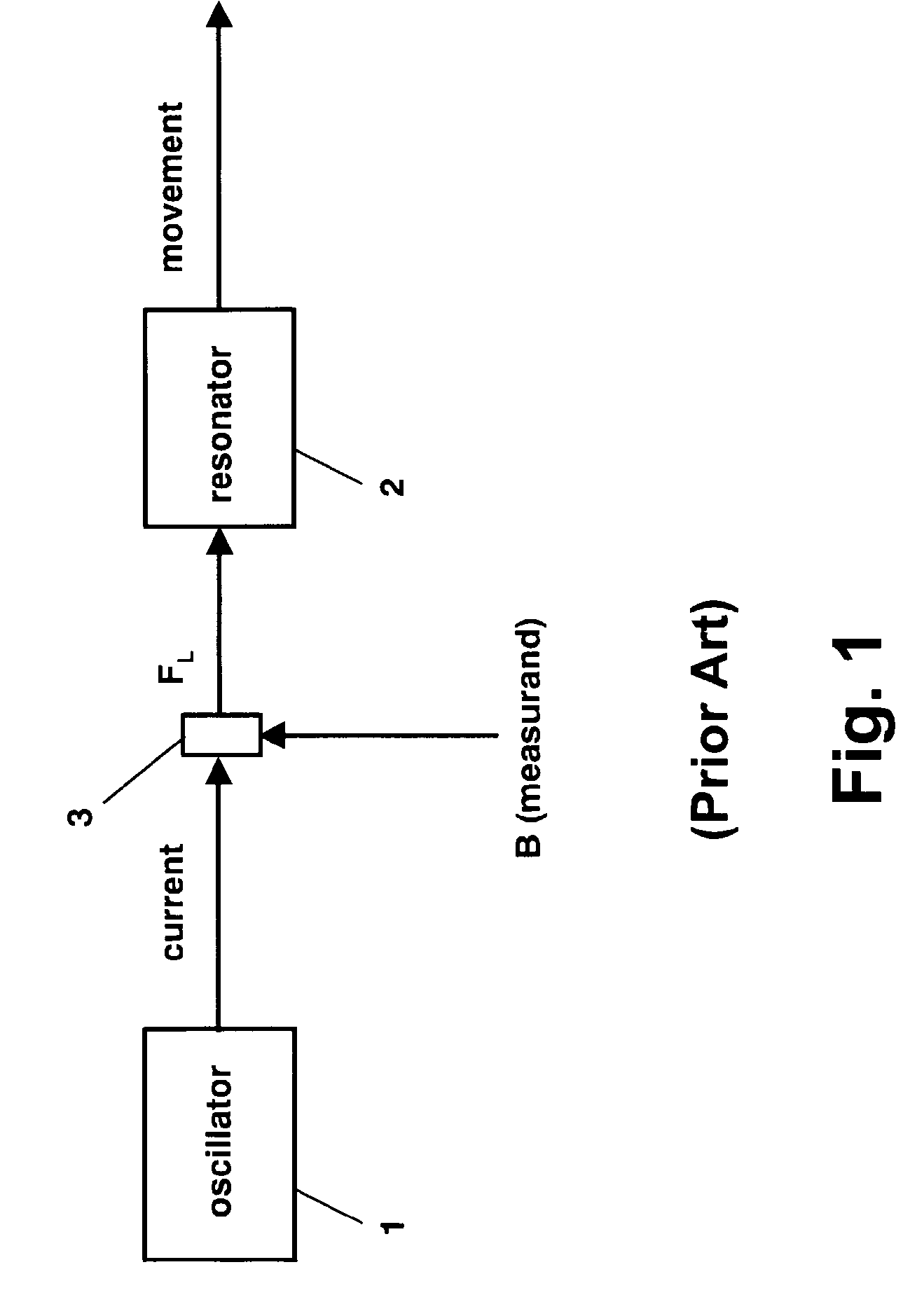
[0021]FIG. 1 shows a prior art open-loop architecture for a resonator-based magnetic field sensor;

[0022]FIG. 2 depicts a prior art closed-loop architecture for a resonator-based magnetic field sensor;

[0023]FIG. 3 represents the basic idea of the present invention;

[0024]FIG. 4 shows a closed-loop architecture according to the present invention;

[0025]FIGS. 5a, 5b are two schematic cross-sections of the microsensor during post-processing;

[0026]FIG. 6 is a micrograph of an implemented cantilever resonator;

[0027]FIG. 7 illustrates a possible embodiment according to FIG. 4, involving a PLL architecture with a frequency-tunable oscillator; and

[0028]FIG. 8 is a detailed schematic of the preferred embodiment according to FIG. 4.

[0029]As already addressed above, FIG. 1 shows a basic layout with an oscillator 1 and a resonator 2. The oscillator 1 provides an AC current, pref...


PUM


Abstract

The resonator-based magnetic field sensor system has an oscillatory member as resonator, means for driving an electrical current through said resonator such that its resonance frequency is altered by an external magnetic field to be measured (measurand), and means for detecting or measuring said altered resonance frequency. A secondary excitation of the resonator is effected to determine the said altered resonance frequency from which the measurand can be deduced. In the preferred embodiment, the secondary excitation is included in a closed loop, thus creating an oscillator vibrating at the altered resonance frequency. Though it is known to use the oscillation amplitude of a suitable resonator for this purpose, the novel sensor system identifies and / or measures the frequency (not the amplitude) of the oscillation, which is a function of the magnetic field to be measured.

Description

FIELD OF THE INVENTION[0001]This invention relates to magnetic field sensing and in particular, to a system and a technique which exploit a mobile mechanical structure to provide a magnetic field sensor (magnetometer) offering a frequency as output.BACKGROUND OF THE INVENTION[0002]Resonator-based magnetic field sensors can principally be divided in two categories, depending on the origin of the magnetic force used to generate or modify the movement of the resonator. In a first case, a current flowing through the resonator creates a Lorentz force in the presence of the magnetic field to be measured (termed measurand in the following). In a second case, the measurand passively generates a torque on a magnetic material fixed to or deposited on the resonator.[0003]In the frame of magnetic field sensors fabricated with microelectromechanical system (MEMS) technologies, numerous resonating-structure types can be exploited in many different oscillation modes. Beams [V. Beroulle, Y. Bértran...

Claims


Application Information

Patent Timeline
IPC IPC(8): G01R33/028
CPCG01R33/028
Inventor SUNIER, ROBERTBRAND, OLIVERVANCURA, TOBIAS A.
Owner SENSIRION AG
Learn More