Signal generating appartus, filter apparatus, signal generating method and filtering method

a signal generating apparatus and signal generating method technology, applied in the direction of generating/distributing signals, pulse techniques, counting chain synchronous pulse counters, etc., can solve the problem of increasing frequency being handled, and achieve the effect of keeping power consumption low and power consumption low

Inactive Publication Date: 2009-01-15
SONY CORP
View PDF6 Cites 19 Cited by
  • Summary
  • Abstract
  • Description
  • Claims
  • Application Information

AI Technical Summary

Benefits of technology

[0011]Thus, the present invention is provided in view of the above described issue, and it is desirable to provide a novel and improved signal generating apparatus, filter apparatus, signal generating method and filtering method which make it possible to generate a number of pulse signals where periods when the signal level is at a first level do not overlap while keeping the power consumption low.
[0014]The transition time point changing portion may be provided with a logic unit for generating one pulse signal by operating a logical product of a first base signal generated by the multiphase signal generating portion and an inverted signal of the base signal having the predetermined phase difference relative to the first base signal. In this configuration, a number of pulse signals where periods during which the signal level is at the first level do not overlap can be generated without operating a number of shift registers, and therefore, the power consumption can be kept low.
[0018]In this configuration, the multiphase oscillating portion generates a number of base signals and the transition time point changing portion changes the time point when each of the base signals transition from the first level to the second level to a time point when or before the base signal having the predetermined phase delay relative to the base signal transitions from the second level to the first level. That is to say, the transition time point changing portion can generate a number of pulse signals where the periods during which the signal levels are at the first level do not overlap on the basis of the base signals generated by the multiphase oscillation portion. In addition, the switching portion allows the respective first capacitors to sample input signals in sequence on the basis of the number of pulse signals generated by the transition time point changing portion. Thus, it is not necessary for the filter apparatus to operate a great number of shift registers in order to generate the pulse signals, and therefore, the power consumption can be kept low.
[0019]The transition time point changing portion may be provided with a logic unit for generating one pulse signal by operating a logical product of a first base signal generated by the multiphase signal generating portion and an inverted signal of the basic signal having the predetermined phase difference relative to the first base signal. In this configuration, a number of pulse signals where periods when the signal levels are at the first level do not overlap can be generated without operating a great number of shift registers, and therefore, the power consumption can be kept low.

Problems solved by technology

As described above, however, when a number of shift registers are driven in order to generate a control signal to be supplied to a charge domain filter circuit, the power consumption increases as the frequency being handled increases.
In addition, multiphase clock signals generated by the ring oscillator have overlapping on periods, and therefore, can be hardly used as a control signal and supplied to the charge domain filter circuit.

Method used


Image

  • Signal generating appartus, filter apparatus, signal generating method and filtering method
  • Signal generating appartus, filter apparatus, signal generating method and filtering method
  • Signal generating appartus, filter apparatus, signal generating method and filtering method

Examples


Embodiment Construction

[0043]Hereinafter, preferred embodiments of the present invention will be described in detail with reference to the appended drawings. Note that, in this specification and the appended drawings, structural elements that have substantially the same function and structure are denoted with the same reference numerals, and repeated explanation of these structural elements is omitted.

[0044]The components of the “best mode for carrying out the invention” are described in the following order.

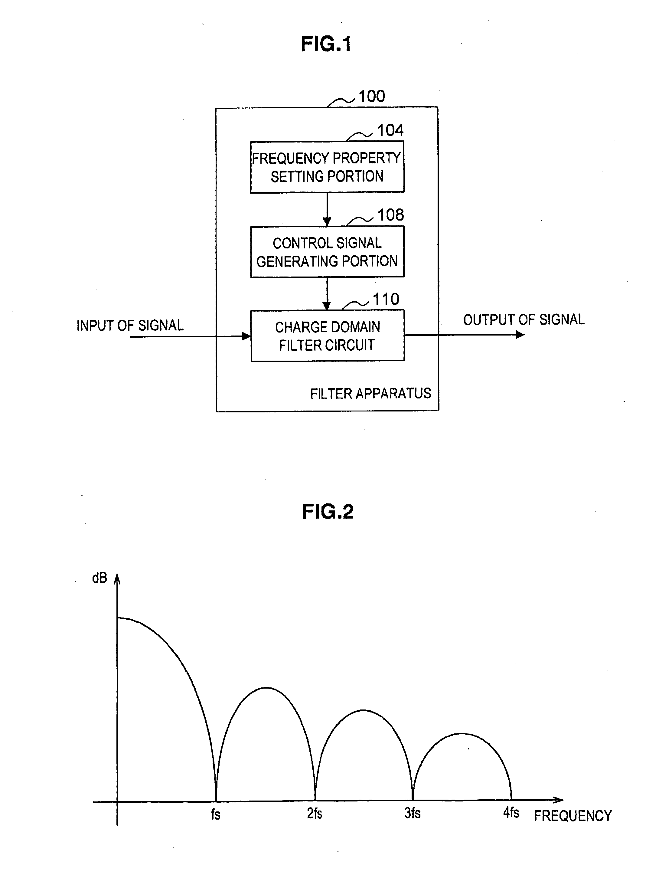
[0045][1] Outline of filter apparatus according to present embodiment

[0046][2] Objects of clock pulse generating circuit which relate to present embodiment

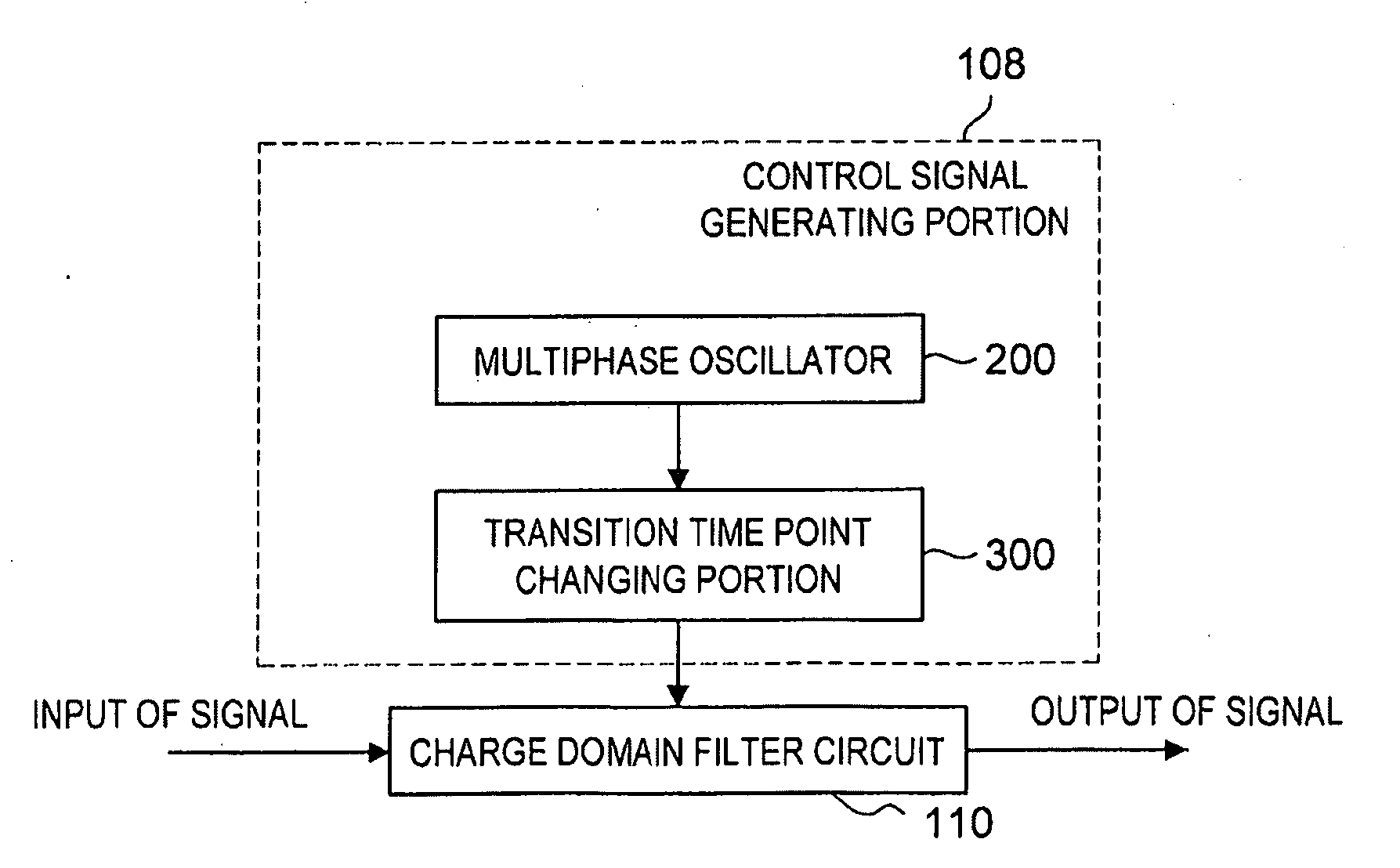
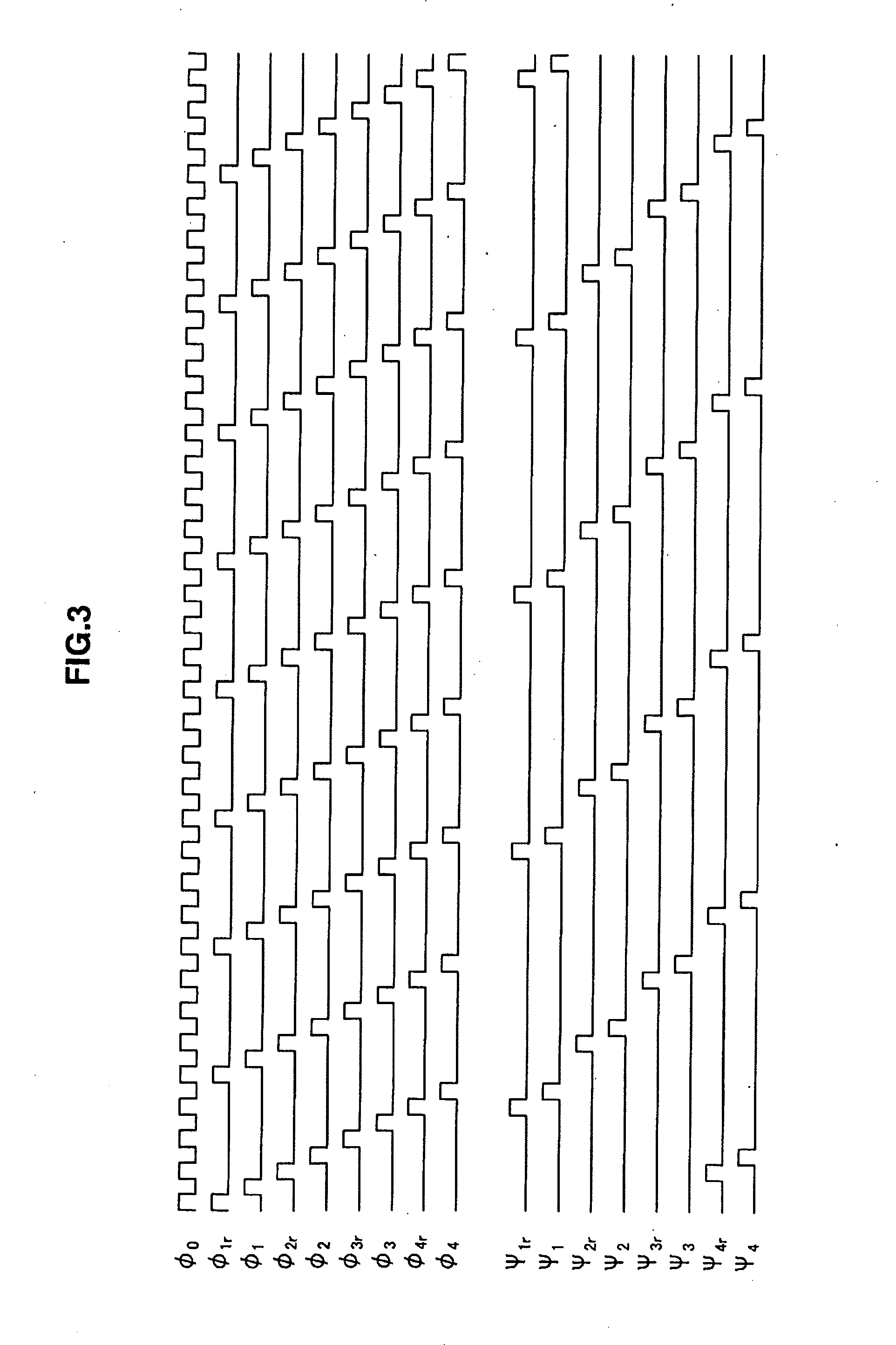
[0047][3] Control signal generating portion that forms filter apparatus

[0048][3-1] First example of configuration of transition time point changing portion

[0049][3-2] Second example of configuration of transition time point changing portion

[0050][3-3] Third example of configuration of transition time point changing portion

[0051][4] Filtering method u...


PUM


Abstract

There is provided a signal generating apparatus including: a multiphase oscillating portion for generating a number of base signals having the same frequency and a predetermined phase difference of which the signal level transitions between a first level and a second level, and where periods during which the signal level of any given base signal is at the first level and the signal level of the next base signal having the predetermined phase delay relative to the given base signal is at the first level overlap; and a transition time point changing portion for generating a pulse signal by changing the time point when each base signal transitions from the first level to the second level to a time point before the next base signal transitions from the second level to the first level.

Description

CROSS REFERENCES TO RELATED APPLICATIONS[0001]The present invention contains subject mater related to Japanese Patent Application JP 2007-183484 filed in the Japan Patent Office on Jul. 12, 2007, the entire contents of which being incorporated herein by reference.BACKGROUND OF THE INVENTION[0002]1. Field of the Invention[0003]The present invention relates to a signal generating apparatus, a filter apparatus, a signal generating method and a filtering method.[0004]2. Description of the Related Art[0005]In wireless communications, various types of data, such as animation image data, still image data and music data, is transmitted and received. In recent years, the amount of the various types of data described above has tended to increase as the precision has increased, and therefore, a higher communication speed (transmitting and receiving performance) has become required for wireless communication. In general, a wide range of frequency bands is required in order to achieve high-speed...

Claims


Application Information

Patent Timeline
Patent Type & Authority Applications(United States)
IPC IPC(8): H03K3/00
CPCH03H19/004H03K23/54H03K5/15093H03K3/0315
Inventor YOSHIZAWA, ATSUSHIIIDA, SACHIO
Owner SONY CORP
Why Eureka
Try Eureka