Device for coupling between a plasma antenna and a power signal generator

Active Publication Date: 2009-01-15
THALES SA
View PDF5 Cites 2 Cited by
  • Summary
  • Abstract
  • Description
  • Claims
  • Application Information

AI Technical Summary

Benefits of technology

[0006]One object of the present invention is a device for coupling between a plasma column serving as an antenna and a power signal generator, a device which allows a very good transfer of power between the electric generator and the plasma column when the latter is

Problems solved by technology

In the low frequency (L.F.), and very low frequency (V.L.F.) and extremely low frequency (E.L.F.) domains, the height of the antennas of the quarter-wave type should reach several hundreds of meters to several hundreds of kilometers (for example 750 m to 100 kHz), which makes them very difficult to construct or even unrealizable.
In addition, they can in no circumstances be easily moved.
However, in all these kno

Method used


Image

  • Device for coupling between a plasma antenna and a power signal generator
  • Device for coupling between a plasma antenna and a power signal generator
  • Device for coupling between a plasma antenna and a power signal generator

Examples


Embodiment Construction

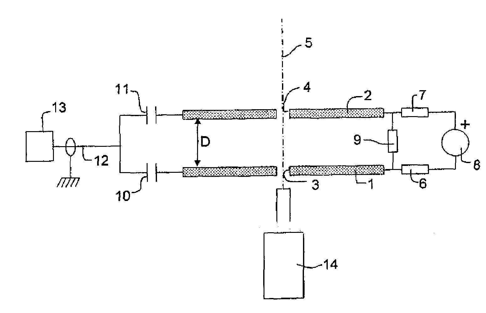
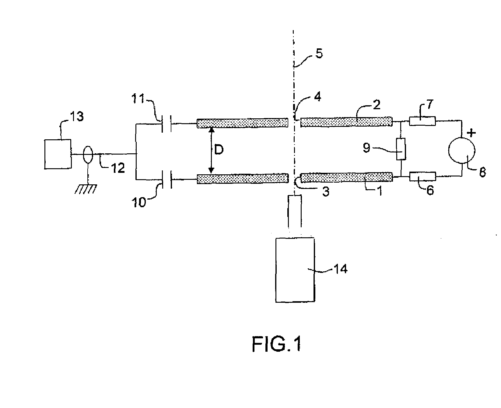
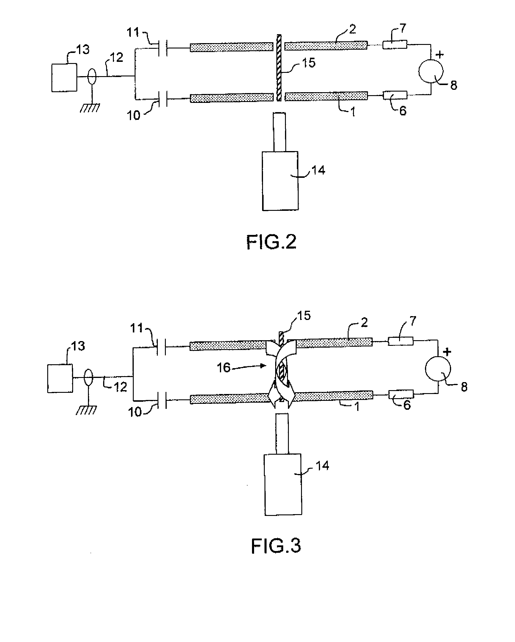
[0015]The present invention is described below with reference to the creation of an ionized air column, and it is well understood that the ionization of this column may be reduced to a filament ionization at the axis of symmetry, as described in the above-mentioned French patent, when a laser of the femtosecond type is used. It is also well understood that the preferred embodiment of the device of the invention, as described below, comprises two electrodes pierced with coaxial holes, but the device of the invention may comprise a higher number of electrodes. The device described below is represented in a position oriented so that the plasma column that it allows to be created is vertical, but it is well understood that this device may have any other orientation so that the antenna is for example horizontal. The plasma antenna obtained according to the invention is described in this instance as a transmission antenna, but it is well understood that it may also be used for reception, ...


PUM


Abstract

The present invention relates to a device for coupling between a plasma column serving as an antenna and an electric power signal generator, associated with a laser. This device comprises at least two conducting electrodes, each pierced with a hole, these holes being coaxial, the electrodes being connected on the one hand to a high voltage direct current source and on the other hand to power signal alternating current source, the laser(s) being placed do that its (their) beam arrives along the axis of said holes of the electrodes.

Description

CROSS REFERENCE TO RELATED APPLICATIONS[0001]The present Application is based on International Application No. PCT / EP2007 / 051177, filed on Feb. 7, 2007, which in turn corresponds to French Application No. 0601075 filed on Feb. 7, 2006, and priority is hereby claimed under 35 USC §119 based on these applications. Each of these applications are hereby incorporated by reference in their entirety into the present application.FIELD OF THE INVENTION[0002]The present invention relates to a device for coupling between a plasma antenna and a power signal generator and a method for using a plasma antenna comprising such a coupling device.DESCRIPTION OF RELATED ART[0003]Conventional (metal) wireless antenna usually operate in a narrow frequency band, and their dimensions are inversely proportional to the operating wavelength. In the low frequency (L.F.), and very low frequency (V.L.F.) and extremely low frequency (E.L.F.) domains, the height of the antennas of the quarter-wave type should reac...

Claims


Application Information

Patent Timeline
IPC IPC(8): H01Q1/26
CPCH05H1/46
Inventor MARQUIS, EMMANUEL
Owner THALES SA
Why Eureka
Try Eureka