Antenna structure and wireless communication apparatus including same

a technology of wireless communication apparatus and antenna structure, which is applied in the direction of antenna details, electrically short antennas, antennas, etc., can solve the problems of difficulty in meeting the demand for multiple bands, and achieve the effect of increasing the electrical length of the driven radiating electrode without increasing the size reducing the size of the antenna structure, and increasing the electrical length of the driven radiating electrod

Inactive Publication Date: 2009-01-15
MURATA MFG CO LTD
View PDF9 Cites 19 Cited by
  • Summary
  • Abstract
  • Description
  • Claims
  • Application Information

AI Technical Summary

Benefits of technology

[0032]Furthermore, the driven radiating electrode has such a form that the feeding end and the open end thereof are provided adjacent to each other with a space therebetween, and a current path between the feeding end and the open end has a loop shape. Thus, advantageously, it becomes readily possible to adjust the base resonant frequency and the harmonic resonant frequency of the driven radiating electrode. That is, since the driven radiating electrode has such a form that the feeding end and the open end thereof are provided adjacent to each other with a space and a current path between the feeding end and the open end has a loop shape, a capacitor is formed between the feeding end and the open end. This capacitor contributes more to the harmonic resonant frequency than to the base resonant frequency. Therefore, with the capacitor between the feeding end and the open end, it is possible to adjust the harmonic resonant frequency of the driven radiating electrode without substantially changing the base resonant frequency. That is, for example, by setting the electrical length between the feeding end and the open end of the driven radiating electrode to be such an electrical length that a predetermined base resonant frequency is achieved, and setting the capacitor between the feeding end and the open end to have a such a magnitude that a predetermined harmonic resonant frequency is achieved, it is possible to adjust the base resonant frequency and the harmonic resonant frequency independently of each other. Thus, it becomes readily possible to set both the base resonant frequency and the harmonic resonant frequency of the driven radiating electrode individually to predetermined frequencies.
[0033]Furthermore, since the driven radiating electrode has such a shape that the current path between the feeding end and the open end has a loop shape, it is possible to increase the electrical length of the driven radiating electrode without increasing the size of the driven radiating electrode. Thus, it is possible to reduce the size of the base, i.e., to reduce the size of the antenna structure.

Problems solved by technology

Even with the antenna structure 40 having an increased bandwidth as described above, it has been difficult to satisfy the demand for multiple bands due to the insufficiency of frequency bands that can be used for wireless communication.

Method used


Image

  • Antenna structure and wireless communication apparatus including same
  • Antenna structure and wireless communication apparatus including same
  • Antenna structure and wireless communication apparatus including same

Examples


first embodiment

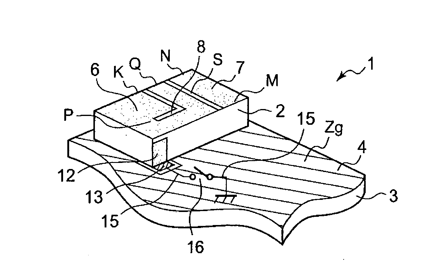
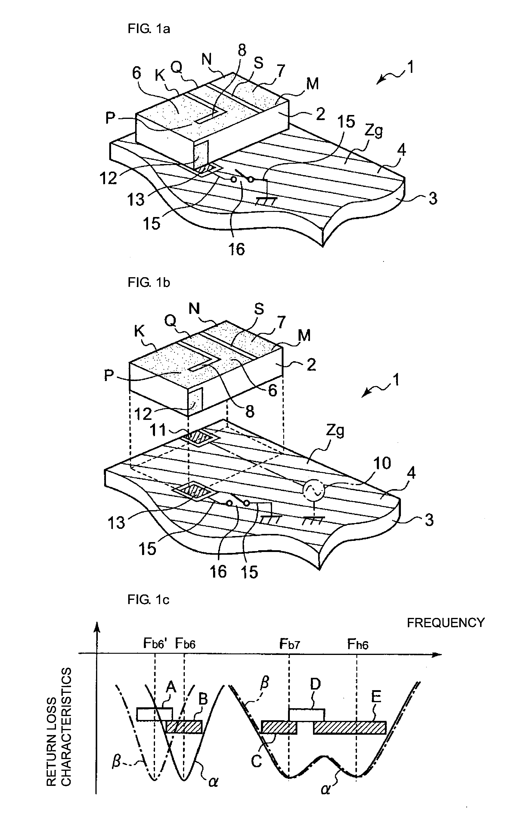
[0086]FIG. 1a is a schematic perspective view showing an antenna structure according to a first embodiment, and FIG. 1b is a schematic exploded view of the antenna structure shown in FIG. 1a. An antenna structure 1 according to the first embodiment includes a base 2 having a rectangular parallelepiped shape. The base 2 is formed of a dielectric material, and is mounted in a ground region Zg (i.e., a region where a ground electrode 4 is formed) on a circuit board 3. The dielectric material forming the base 2 is, for example, a ceramic, a resin, or a dielectric material composed of a mixture of a resin material and ceramic powder so as to have an adjusted dielectric constant. The base 2 may have either a single-layer structure or a multi-layer structure.

[0087]In the first embodiment, on a top surface of the base 2, a driven radiating or feeding electrode 6 and a parasitic radiating or non-feeding electrode 7 are disposed adjacent to each other via (i.e., separated by) a space S. The d...

second embodiment

[0108]Now, a second embodiment will be described. In the description of the second embodiment, components that are the same as those in the first embodiment are designated by the same numerals, and repeated description of the common components will be omitted.

[0109]In the second embodiment, as shown in FIG. 8a, a plurality of (two in the example shown in FIG. 8a) capacitance loading electrodes 12 (12a and 12b) are provided on the base 2. By forming a plurality of capacitance loading electrodes 12 on the base 2 as described above, it is possible to form a plurality of types of antenna structures using the base 2 having formed thereon the plurality of capacitance loading electrodes 12, the driven radiating electrode 6, the parasitic radiating electrode 7, and so forth (such a base 2 will hereinafter be referred to as an antenna component). The plurality of capacitance loading electrodes 12 may be formed so that different capacitances can be loaded in the harmonic-mode zero-voltage reg...

third embodiment

[0115]Now, a third embodiment will be described. In the description of the third embodiment, components that are the same as those in the first and second embodiments are designated by the same numerals, and repeated description of the common components will be omitted.

[0116]In the third embodiment, in addition to the configuration of the first or second embodiment, the parasitic radiating electrode 7 has a loop-shaped current path. For example, in an example shown in FIG. 9a, the parasitic radiating electrode 7 has a slit 26 formed so as to cut in from an end edge of the parasitic radiating electrode 7. At the electrode end edge on the side of the opening of the cutting of the slit 26, with the slit 26 in the middle, one end N serves as a shorted end electrically connected to the ground electrode 4, and the other end M serves as an open end. A current path between the shorted end N and the open end M is a loop-shaped path extending around the slit 26 and connecting the feeding end ...


PUM


Abstract

In an antenna structure in which a base is mounted in a ground region on a circuit board, the base having formed thereon a driven radiating electrode and a parasitic radiating electrode, the parasitic radiating electrode causing multiple resonance at least in a harmonic resonant frequency band of the driven radiating electrode, capacitance loading means for loading a capacitance to a harmonic-mode zero voltage region of the driven radiating electrode is provided. The capacitance loading means is electrically connected to a ground electrode in the ground region on the circuit board via a grounding conduction path and switching means. By switching the switching means ON/OFF, capacitance loading by the capacitance loading means to the harmonic-mode zero voltage region of the driven radiating electrode is switched ON/OFF to switch a base resonant frequency in a base resonant frequency band of the driven radiating electrode.

Description

CROSS-REFERENCE TO RELATED APPLICATIONS[0001]This is a continuation under 35 U.S.C. §111(a) of PCT / JP2006 / 323818 filed Nov. 29, 2006, and claims priority of JP2006-036830 filed Feb. 14, 2006, both incorporated by reference.BACKGROUND[0002]1. Technical Field[0003]The present invention relates to antenna structures provided in wireless communication apparatuses, such as cellular phones, and to wireless communication apparatuses including the antenna structures.[0004]2. Background Art[0005]FIG. 13a is a schematic perspective view showing an example of an antenna structure (e.g., refer to Patent Document 1). The antenna structure 40 includes a dielectric base 41 having a rectangular parallelepiped shape, and a ground electrode 42 is formed on the bottom surface of the dielectric base 41. Furthermore, on the top surface of the dielectric base 41, a driven radiating or feeding electrode 43 and a parasitic radiating or non-feeding electrode 44 are provided adjacent to each other, separated...

Claims


Application Information

Patent Timeline
Patent Type & Authority Applications(United States)
IPC IPC(8): H01Q9/00H01Q1/38H01Q5/10
CPCH01Q1/243H01Q9/0421H01Q5/392H01Q5/364H01Q9/0442
Inventor NAGUMO, SHOJIFURUYA, KAZUYUKISHIMIZU, MIEFUJII, HIROTAKA
Owner MURATA MFG CO LTD
Why Eureka
Try Eureka