Photoelastic modulator

a modulator and photoelastic technology, applied in the field of spectroscopy and spectropolarimetry, can solve the problems of affecting the efficiency of the modulator, so as to reduce the reduce the unwanted effect of other modes and reflections, and reduce the effect of interfering vibration and reflection

Inactive Publication Date: 2009-01-15
ENDEAVOUR INSTR
View PDF10 Cites 2 Cited by
  • Summary
  • Abstract
  • Description
  • Claims
  • Application Information

AI Technical Summary

Benefits of technology

[0015]Thus, longitudinal standing waves may be excited in the photoelastic modulator for the optical modulation and phase modulation of light, while reducing interfering vibration and reflections inside the modulator.
[0016]This approach attempts to separate the lengthwise extension mode of the transducer from other modes, or to at least have the lengthwise extension mode dominate, thereby minimising the unwanted effects of other modes and reflections. In an elongated rod or pipe shaped solid, transverse perturbation is induced by the longitudinal wave's propagating along the longitudinal axis; these waves are called Lamb waves.
[0017]With the isolation of the lengthwise extension mode, a single block of optical material can be used for the construction of a complete photoelastic modulator. This has the advantage of minimising the temperature sensitivity while retaining the advantages of the Canit-Badoz single optical block arrangement to avoid the precise dimensional matching in the process of building the Kemp PEM. Pure or nearly pure longitudinal standing wave mode is maintained.
[0018]The transducer may be in the form of a compound transducer or a set of transducers. In one embodiment, the transducer comprises an array of narrow strips to minimise vibration modes perpendicular to the predefined direction.

Problems solved by technology

However, this form of PEM is sensitive to variations in ambient temperature, which poses difficulties in applications outside temperature controlled laboratories.
The Canit-Badoz device employs so-called “shear coupling” to achieve high efficiency, which they effect by adhering a thin slab of piezoelectric ceramic transducer to one surface of a rectangular optical element, but this creates new problems.
The surface induced longitudinal acoustic standing wave that is the driving force for creating optical birefringence causes considerable unwanted vibrations and acoustic reflections.
These unwanted components tend to interfere with each other and degrade the purity of the polarisation modulation.
In practice, the suggested use of two piezoelectric transducers—one on the top surface and one on the bottom surface of the PEM body—has been shown to operate with low efficiency, and this design has been mentioned little in the measurement of polarisation.
Although the Canit-Badoz device is effective, no experimental evidence or theoretical study has yet verified the suggested mechanism.
Further, the shear coupling create considerable internal reflections together with some resonances at different acoustic frequencies; these perturb the normal longitudinal standing wave.
Although the frequencies are separated from the desired longitudinal frequency, it appears likely that polarisation purity is adversely—if transiently—affected.
The acoustical spectrum is relatively easy to measure, but it has proved to be extremely difficult to visualise them as acoustic waves and to analysis their individual components.
However, owing to the inherent limitations of the Canit-Badoz driving scheme, the PEM of WO 06 / 079168 also has limitations such that, for example, a two block structure remains preferable, with an optical block of smaller cross-section employed to minimise the propagation of unwanted vibration.

Method used


Image

  • Photoelastic modulator
  • Photoelastic modulator
  • Photoelastic modulator

Examples


first embodiment

[0064]FIG. 6 is a schematic view of a single-block full wave PEM body 60 according to the present invention. The PEM body 60 comprises a solid block of optical material comprising, in this embodiment, a rectangular block of fused silica. The PEM body 60 includes a rectangular recess 62, formed by masking the upper surface 64 of PEM body 60 and removing material with a particle jet etching (i.e. essentially sand blasting) or chemical etching. Geometrically, the recess 62 is the opposite of a mesa. The size of recess 62 is less than that of the transducer to be affixed in length (i.e. in the Y direction) but wider than the transducer (i.e. in the X direction).

[0065]If the PEM body is, instead, to be used as part of a two block PEM, the material of the two blocks is preferably a solid material of the same chemical constituent. However, only the optical block is in such embodiments of high optical quality such as in spectral coverage, and with very low residual birefringence.

[0066]The r...

second embodiment

[0067]FIG. 7 is a single-block half-wave mode PEM body 70 according to the present invention. The PEM body 70, like PEM body 60 of FIG. 6, comprises a solid block of optical material comprising a rectangular block of fused silica. PEM body 70 includes a recess 72, comparable to recess 62 of PEM body 60 of FIG. 6, formed in upper surface 74. In addition, however, PEM body 70 includes a second recess 76 formed in bottom surface 78 of the PEM body 70.

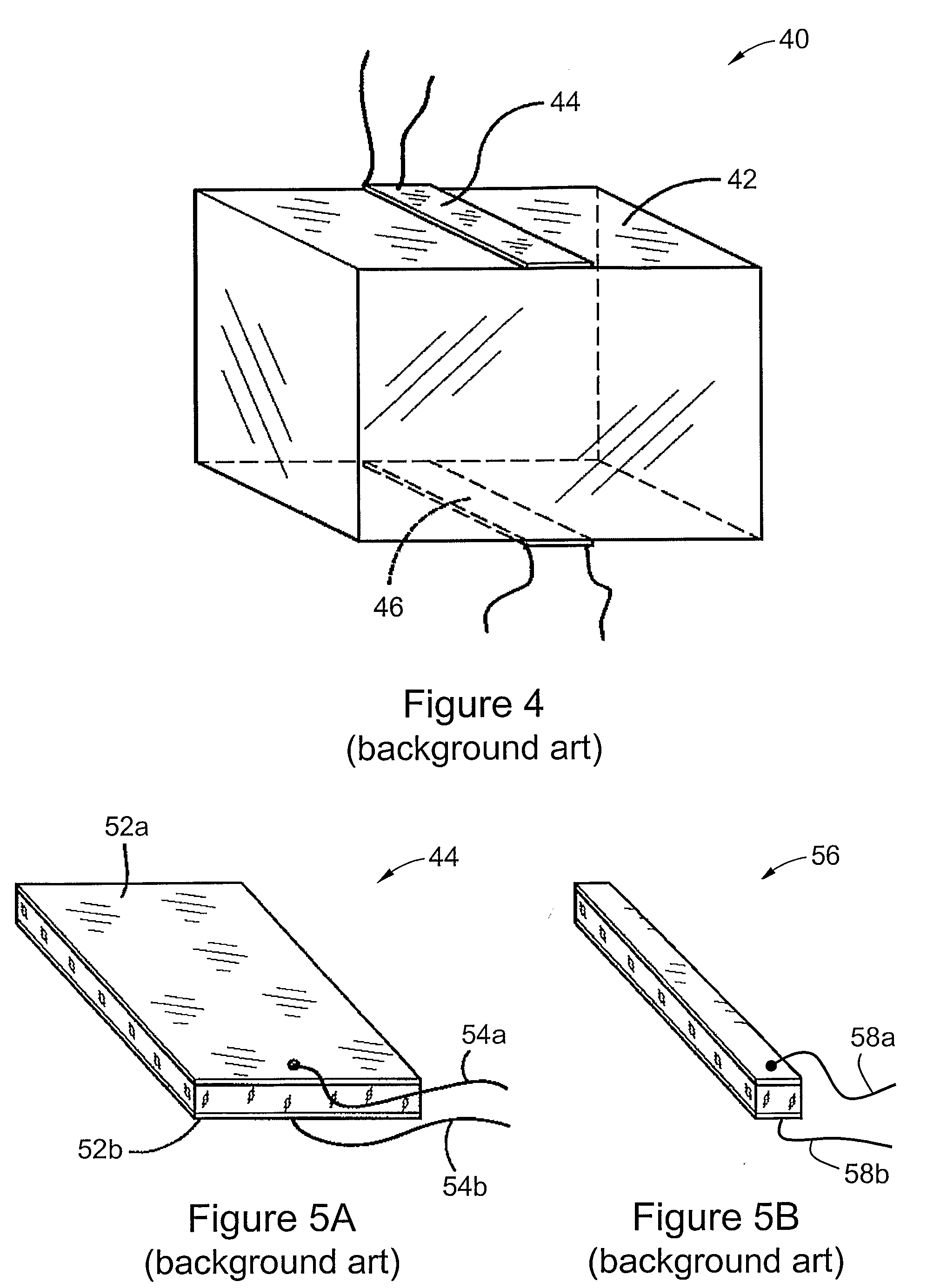
[0068]The ultimate PEM comprises PEM body 60 and a piezoelectric transducer (such as transducer 44 of FIGS. 4 and 5A). FIG. 8 is a schematic plan view of PEM body 60 (or equivalently PEM body 70), with a piezoelectric transducer 80 (with electrical leads 82, 84) attached thereto over recess 62. The transducer 80 can be a single slab of piezoelectric material (such as PZT-5 ceramic) but most conveniently either a number of separated narrow strips or a multiple strip array in a single piece of piezoelectric material. After the PEM's sensor (...

third embodiment

[0075]FIG. 9 is a schematic view of a single-block half-wave mode PEM body 90 according to the present invention. The PEM body 90 comprises a solid block of optical material comprising a rectangular block of fused silica. The PEM body 90 includes an H shaped recess 92 in its upper surface 94; this shape leaves non-recess portions in the form of contact pads 96a, 96b extending inwardly towards the centre of the recess 92. These contact pads 96a, 96b provide additional contact areas for a piezoelectric transducer, and contact areas for the sensor. This provides a purely extension mode of sensing that minimises the detection of reflections inside the block 90 that might otherwise be transferred to the sensor as noise.

[0076]This embodiment of PEM body is most particularly adapted for use in high stress conditions. PEMs operating in long optical wavelengths, that is from the medium to the far-infrared optical spectral region, requires a strong strain induced birefringence to create suffi...


PUM

PropertyMeasurementUnit
depthaaaaaaaaaa
mechanical couplingaaaaaaaaaa
pressureaaaaaaaaaa

Abstract

A photoelastic modulator, comprising a driving block and a driver transducer for perturbing said block in a predefined direction to establish a standing wave extending longitudinally in said block and hence perpendicularly to said predefined direction. The transducer is affixed to said block at two regions of the transducer mutually displaced in said predefined direction, to minimise the coupling of lateral perturbation perpendicular to the predefined direction. A recess or gap may be provided under the transducer.

Description

RELATED APPLICATION[0001]This application is based on and claims the benefit of the filing date of AU application no. 2006900445 filed 31 Jan. 2006, the content of which is incorporated herein by reference in its entirety.FIELD OF THE INVENTION[0002]The present invention relates to the fields of spectroscopy and spectropolarimetry. Specifically, the invention relates to a photoelastic modulator, for use most particularly in polarised light measurements and the phase modulation of light.BACKGROUND OF THE INVENTION[0003]A photoelastic modulator (PEM) is an optical device for the modulation of polarisation or phase modulation of light. PEMs exploit the photoelastic effect, whereby an optical element exhibits birefringence—that is, the refractive index of the element is different for different components of polarised light—that is proportional to the amount of strain (and hence deformation) induced in the element.[0004]The modern PEM was invented in 1969 by J. C. Kemp (J. C. Kemp, Journ...

Claims


Application Information

Patent Timeline
Patent Type & Authority Applications(United States)
IPC IPC(8): G02F1/01
CPCG02F1/0131G01J4/00G02F1/11
Inventor LING, WILLIAM PUI
Owner ENDEAVOUR INSTR
Why Eureka
Try Eureka