Catalytic process for the preparation of fluorinated halocarbons

Inactive Publication Date: 2009-01-15
BELTER RANDOLPH K
View PDF4 Cites 4 Cited by
  • Summary
  • Abstract
  • Description
  • Claims
  • Application Information

AI Technical Summary

Benefits of technology

[0006]A process is described for the preparation of 2-chloro-1,1,1-difluoroethane by the reaction of 1,2-dichloro-1,1-difluoroethane with hydrogen fluoride. in the presence of a fluorination catalyst. The process utilizes a rate enhancing reagent that is trichloroethylene, is 1-fluoro-1,2,3-trichloroethane or an aromatic rate enhancing reagent having the formula

Problems solved by technology

As this second reaction is more difficult, it is most successfully performed as a high temperature vapor phase reaction over an alumina or chromia catalyst.

Method used


Image

  • Catalytic process for the preparation of fluorinated halocarbons
  • Catalytic process for the preparation of fluorinated halocarbons
  • Catalytic process for the preparation of fluorinated halocarbons

Examples


example 1

Hydrofluorination of 1,2-dichloro-1,1-difluoroethane—without Rate Enhancing Reagent

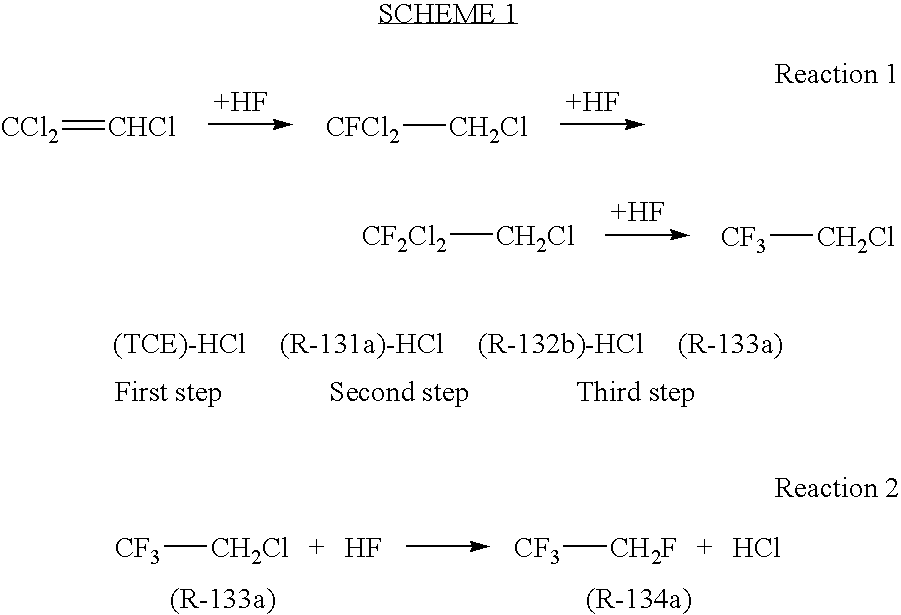
[0016]Seven Hundred and twenty milligrams (0.002 mol) of tantalum pentachloride (TaCl5) was charged into a 250 milliliter reactor. The reactor was evacuated and cooled with ice. Fifty grams (2.5 moles) of anhydrous hydrogen fluoride (HF) was next added to the reactor. The resulting solution was heated with stirring to 140° C. for 60 minutes. The reactor was cooled with ice and 13.4 grams (0.1 mol) of 1,2-dichloro-1,1-difluoroethane (R-132b) was added. The reactor was heated to 140° C. and samples were withdrawn from the reactor headspace. The reaction was monitored by GC. After 1.5 hours, a sample was analyzed. The yield of 2-chloro-1,1,1-trifluoroethane (R-133a) was 36.5%. A repeat example using the same amount of reactants under the same conditions produced a yield of R-133a of 22%.

example 2

Hydrofluorination of 1,2-dichloro-1,1-difluoroethane-15% Rate Enhancing Reagent Added

[0017]Seven Hundred and twenty milligrams (0.002 mol) of tantalum pentachloride (TaCl5) was charged into a 300 milliliter reactor. The reactor was evacuated and cooled with ice. Fifty grams (2.5 moles) of anhydrous hydrogen fluoride (HF) was next added to the reactor. The resulting solution was heated with stirring to 140° C. for 60 minutes. The reactor was cooled with ice and a mixture of 13.4 grams (0.1 mol) of 1,2-dichloro-1,1-difluoroethane (R-132b) and 2.2 grams (0.015 mole) 1-fluoro-1,1,2-trifluoroethane (R-131a) was added. The reactor was heated to 130° C. and samples were withdrawn from the reactor headspace. The reaction was monitored by GC. After 1 hour a sample was analyzed. The yield of 2-chloro-1,1,1-trifluoroethane (R-133a) was 87.5%.

example 3

Hydrofluorination of Trichloroethylene—without Rate Enhancing Reagent

[0018]In a 500 milliliter Hastaloy reactor was placed 7.2 grams of TaF5. The reactor was evacuated, cooled in an ice bath and 120 grams (6 mol) of anhydrous HF were added. The reactor was heated to 100° C. and 131 grams (1 mol) trichloroethylene were added all at one time. The reactor was then rapidly heated to 140° C. and maintained at this temperature for 6 hours. A constant pressure of 500 psi was maintained by venting the hydrogen chloride reaction product. At the conclusion of the reaction period, the contents of the reactor were vented into crushed ice. Analysis of the product obtained from the ice mixture gave a yield of 2-chloro-1,1,1-trifluoroethane of 80%. The residue in the reactor was extracted with 10% hydrochloric acid. The amount of residue was 13 grams and appeared to be a water insoluble oligomeric tar


PUM

PropertyMeasurementUnit
temperatureaaaaaaaaaa

Abstract

A process is described for the preparation of 2-chloro-1,1,1-difluoroethane by the reaction of 1,2-dichloro-1,1-difluoroethane with hydrogen fluoride. in the presence of a fluorination catalyst. The process utilizes a rate enhancing reagent that is trichloroethylene, is 1-fluoro-1,2,3-trichloroethane or an aromatic rate enhancing reagent having the formula
where R is C1 to C6 linear or branched alkyl substituted with at least one halo group, halo or nitro and R′ is C1 to C6 linear or branched alkyl substituted with at least one halo group.

Description

FIELD OF INVENTION[0001]The present invention relates to a process for the preparation of chlorofluoro ethanes. More particularly, a process for the preparation of 2-chloro-1,1,1-trifluoroethane is described that utilizes rate enhancing reagents.DESCRIPTION OF THE RELATED ART[0002]For decades chlorofluorocarbons have been useful chemicals for refrigeration, solvent, foam manufacture and firefighting applications. The refrigerant R-12 (difluorodichloroethane) was the standard refrigerant and found widespread use in automotive air conditioners. The discovery of the harmful nature of chlorofluorocarbons towards the Earth's protective ozone layer led to the outlawing of the manufacture and use of most of these chemicals in the 1989 Montreal Protocol. The most popular non-ozone depleting replacement for R-12 for use in automotive air conditioning units has been R-134a (1,1,1,2-tetraflororoethane). The production of R-134a generally begins with trichloroethylene (TCE) as feedstock for a t...

Claims


Application Information

Patent Timeline
Patent Type & Authority Applications(United States)
IPC IPC(8): C07C17/013
CPCC07C17/206C07C17/21C07C19/12
Inventor BELTER, RANDOLPH K.
Owner BELTER RANDOLPH K
Why Eureka
Try Eureka