
Detecting device, detecting method, and program

a detection device and a technology for detecting methods, applied in the direction of vehicle position/course/altitude control, process and machine control, instruments, etc., can solve the problems of increasing hardware size, complex circuit structure, and inability to terminate the detection process within a predetermined period of time, so as to effectively detect information required to control a vehicle

Inactive Publication Date: 2009-01-15
ORMON CORP
View PDF3 Cites 49 Cited by
  • Summary
  • Abstract
  • Description
  • Claims
  • Application Information

AI Technical Summary

Benefits of technology

[0008]The invention is conceived in view of the above-mentioned circumstance and is designed to effectively detect information required to control a vehicle in accordance with a situation.
[0011]Accordingly, the detection process to be performed can be selected in accordance with the situation of the own vehicle. Moreover, it is possible to effectively detect information used to control the vehicle.
[0016]Accordingly, it is possible to effectively detect the information used to control the vehicle in the situation in which a driver has to be careful.
[0018]Accordingly, it is possible to rapidly and effectively detect the information on the target which a driver has to be careful of.
[0020]Accordingly, it is possible to detect the information on the target which a driver has to be careful of in accordance with the sequence in which a driver has to be careful.
[0023]Accordingly, the detection process to be performed can be selected in accordance with the situation of the own vehicle. Moreover, it is possible to effectively the information used to control the vehicle.

Problems solved by technology

However, appropriate detecting methods of precisely detecting necessary information are generally different from each other in accordance with the targets.
Accordingly, there arises a problem that the detecting process cannot be terminated within a predetermined period of time.
However, in this case, there arise problems that the size of hardware increases, the structure of a circuit becomes complicated, and cost increases.

Method used


Image

  • Detecting device, detecting method, and program
  • Detecting device, detecting method, and program
  • Detecting device, detecting method, and program

Examples


Embodiment Construction

[0045]Hereinafter, an embodiment of the invention will be described with reference to the drawings.

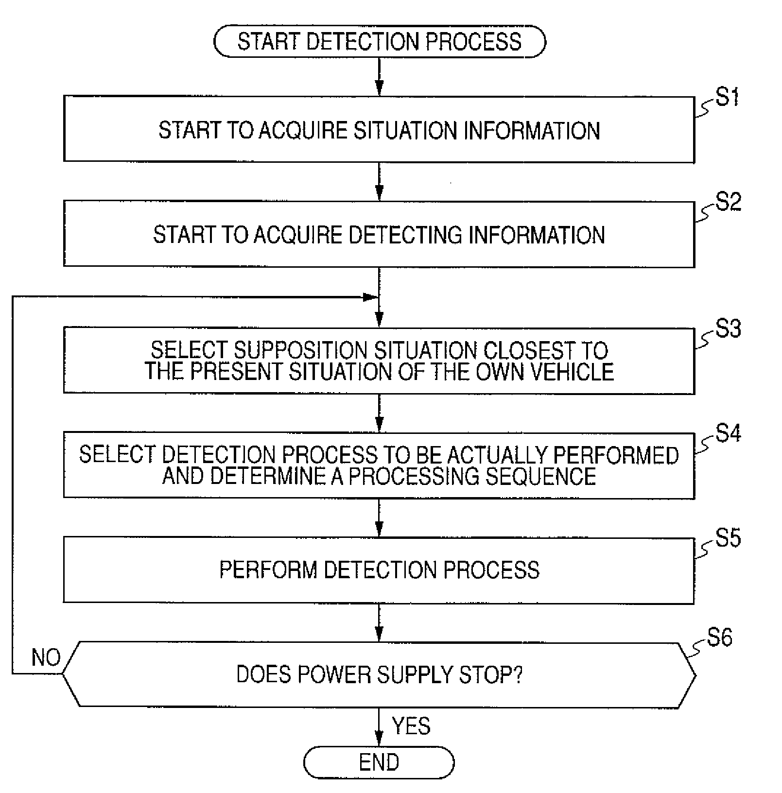
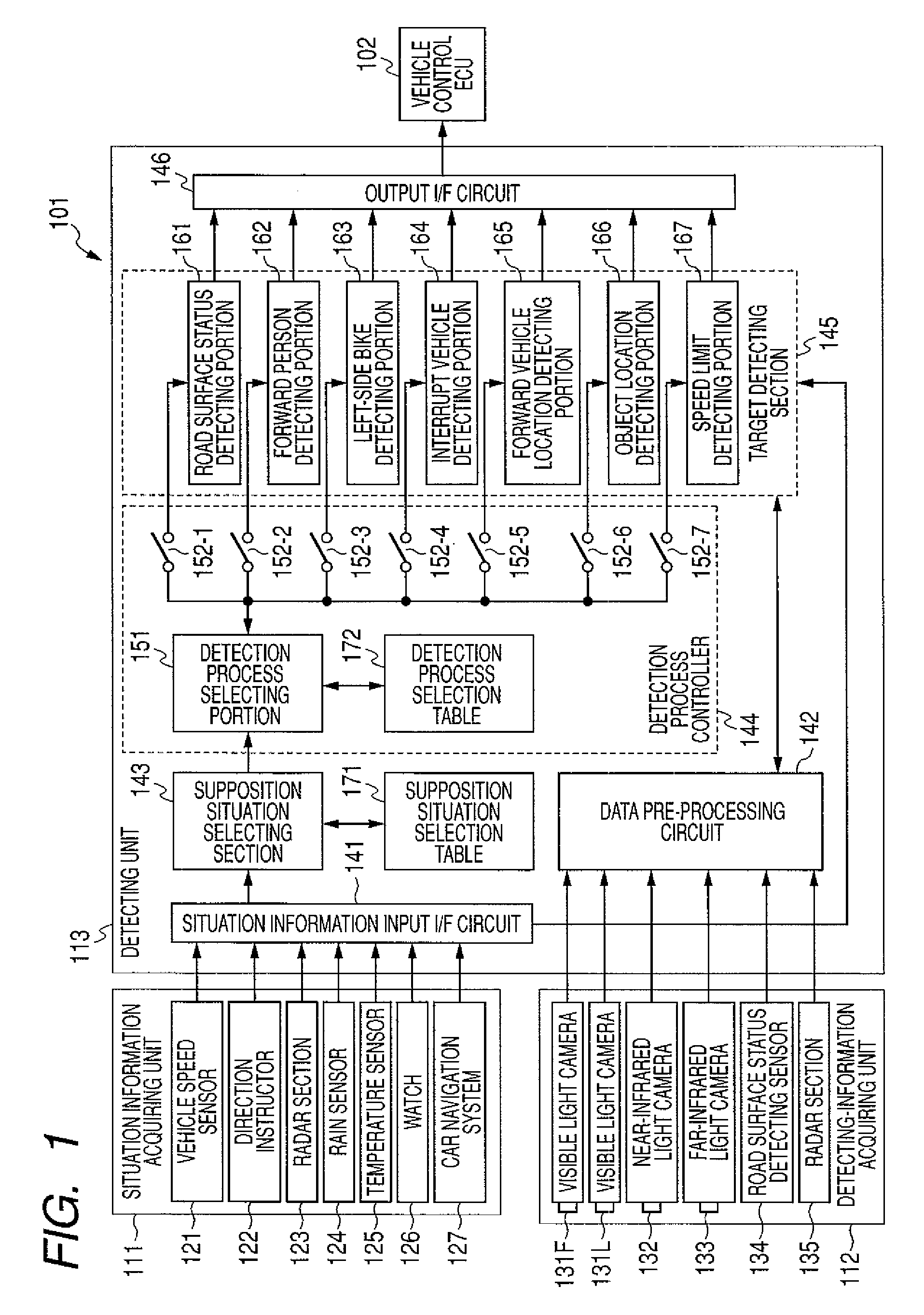
[0046]FIG. 1 is a block diagram illustrating a detecting system according to an embodiment of the invention. A detecting system 101 according to the invention is a system which is provided in a vehicle to detect information on a predetermined target. The information is used to control the vehicle (hereinafter, referred to as an own vehicle).

[0047]The detecting system 101 is configured so as to include a situation-information acquiring unit 111, a detecting-information acquiring unit 112, and a detecting device 113. The situation information acquiring unit 111 includes a vehicle speed sensor 121, a direction instructor 122, a radar section 123, a rain sensor 124, a temperature sensor 125, a clock 126, and a car navigation system 127. The detecting-information acquiring unit 112 includes a visible light camera 131F, a visible light camera 131L, a near-infrared light camera 132, afar-infr...


PUM


Abstract

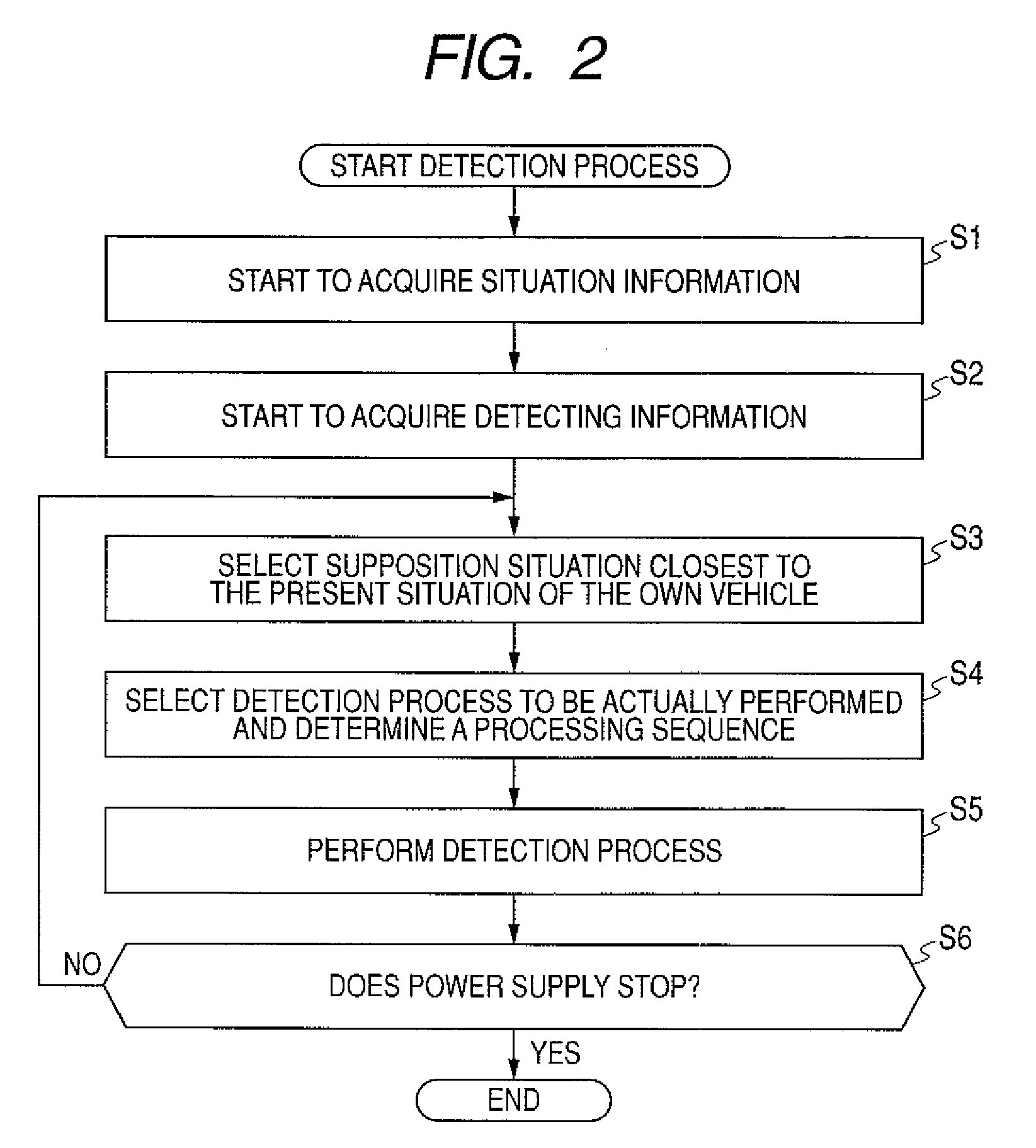
Information necessary to control a vehicle is to be effectively detected in accordance with a situation. A supposition situation selecting section selects a supposition situation closest to the present situation of an own vehicle from a plurality of pre-supposed supposition situations on the basis of situation information acquired from a situation information acquiring unit and a supposition situation selection table through a situation information input I / F circuit. A detection process selecting portion selects a detection process to be actually performed from detection processes which can be performed by each detecting portion of a target detecting section on the basis of the selected supposition situation and a detection process selection table. The invention is applicable to an in-vehicle image processing device.

Description

BACKGROUND OF THE INVENTION[0001]1. Field of the Invention[0002]The present invention relates to a detecting device, a detecting method, and a program, and more particularly relates to the detecting device, the detecting method, and the program capable of effectively detecting information necessary to control a vehicle.[0003]2. Description of Related Art[0004]In the past, there was disclosed a forward monitoring device which detects a forward obstacle such as a forward vehicle, a parked vehicle, and a pedestrian and an interrupting obstacle such as a vehicle which is interrupting in a lane or area of the own vehicle and a pedestrian, in order to detect a location at which the obstacle is located closest to the own vehicle among the detected obstacles as a final obstacle location (for example, see JP-A-2004-280194 (Patent Document 1)).[0005]Recently, there has been the spread of an in-vehicle function which uses information on a predetermined target detected using a photographed surr...

Claims


Application Information

Patent Timeline
IPC IPC(8): B60W40/00
CPCG08G1/16G08G1/165G08G1/166G08G1/167
Inventor UEDA, TADAKAZUASOKAWA, YOSHINOBUITO, YOSHIROIKETANI, TAKASHI
Owner ORMON CORP
Learn More