
Removably attachable card and card retaining device

a technology of attachable cards and retaining devices, which is applied in the field of removable cards, can solve the problems of people forgetting to return cards, cards falling out of wallets, and inconvenience due to the loss of credit cards, and achieves the effect of easy and cost-effective manufacturing

Inactive Publication Date: 2009-01-22
GOETTING THOMAS J
View PDF15 Cites 28 Cited by
  • Summary
  • Abstract
  • Description
  • Claims
  • Application Information

AI Technical Summary

Benefits of technology

[0020]The present invention is an improved information-bearing card and card retaining member for removably securing the card to the card retaining member. The invention is applicable to cards constructed of a substantially rigid yet deformable material such that the shape of the card may be altered by the application of a mechanical force, and upon the cessation of that force the card returns to its original shape.
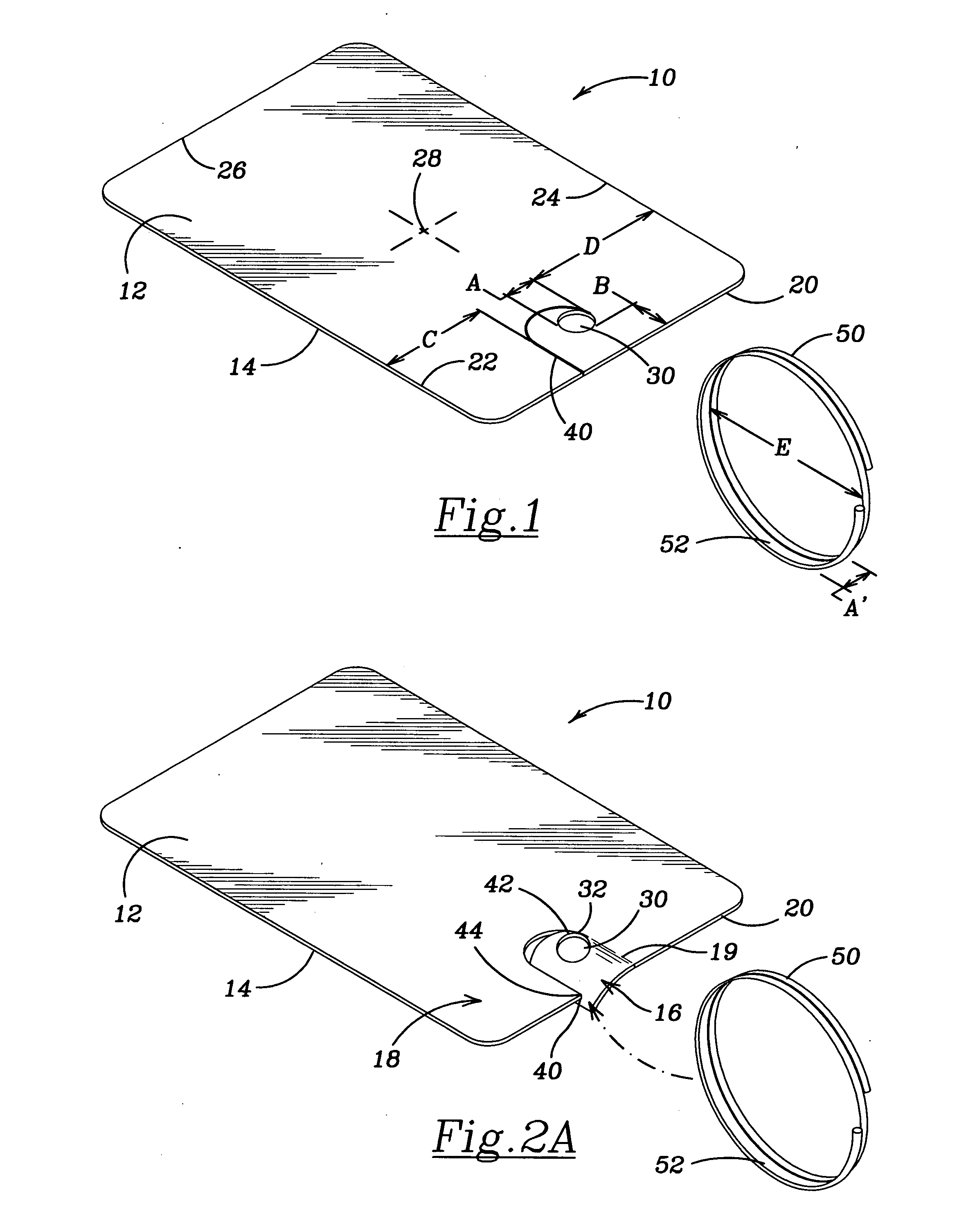
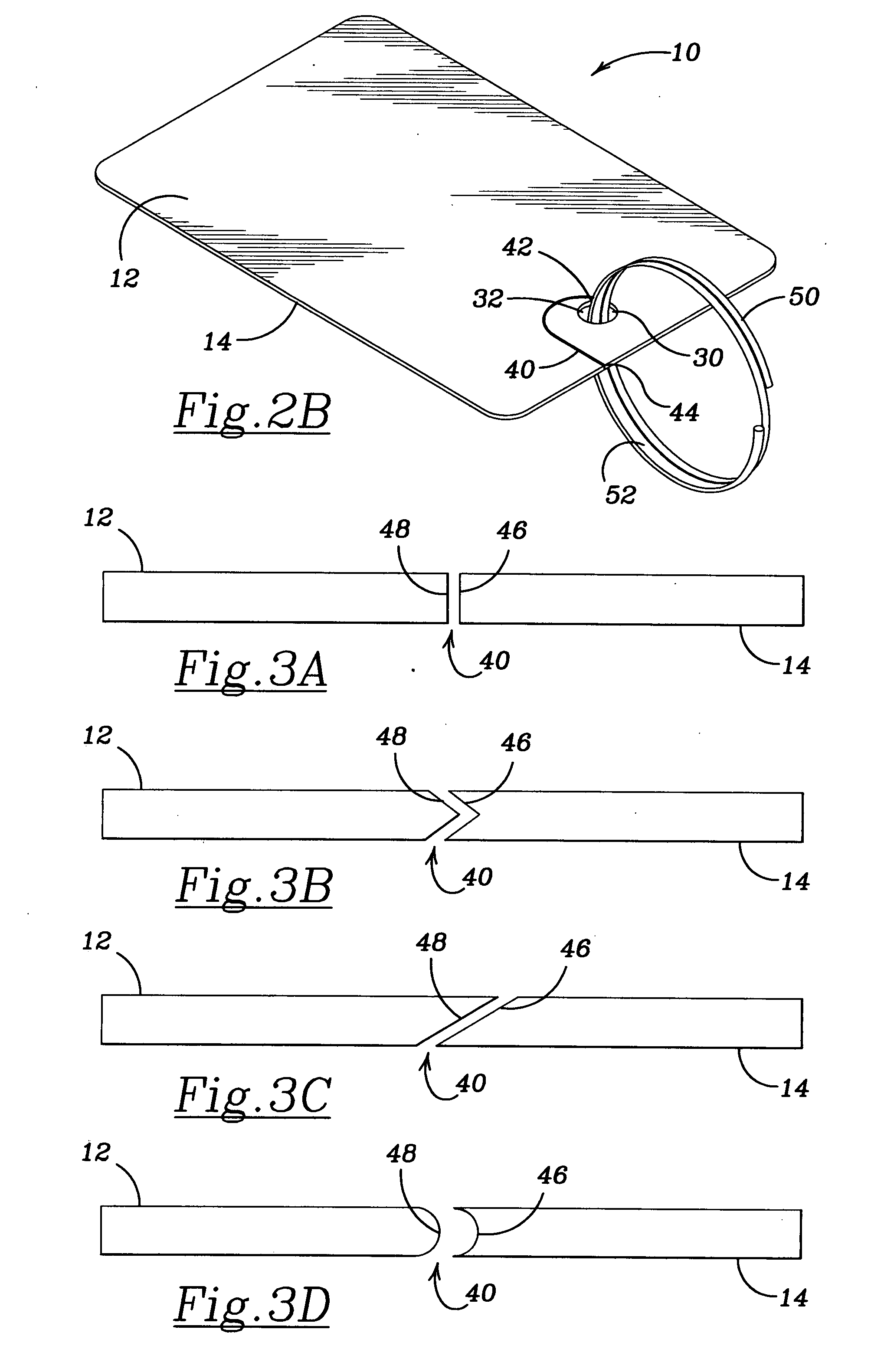
[0021]The invention requires the card to be configured with an aperture and a slot, with the aperture being located within the body of the card and the slot running from the aperture to an edge of the card. The card retaining member may be a closed continuous loop of any suitable shape, such as substantially circular, ovoid, polygonal, or irregular shape, or the card retaining member may be a non-closed member having a substantially linear shape, such as an electric cord, a cable, a wire, a pipe, a rod, etc., onto which the card may be placed by deforming the shape of the card to open the slot and pass a portion of the card retaining member through the slot and into the aperture. The card may be detached from the card retaining member by deforming the shape of the card to open the slot and pass the card retaining member out of the aperture and through the slot. This operation of attaching and detaching the card from the card retaining member may be repeated as often as desired. The configuration and placement of the aperture and the slot on the card provide secure attachment of the card and ease of use. That is, they cooperatively permit easy attachment and detachment of the card from the card retaining member while limiting the risk of accidental detachment of the card when it is attached to the card retaining member. The invention contemplates the use of one or more cards with a single card retaining member.
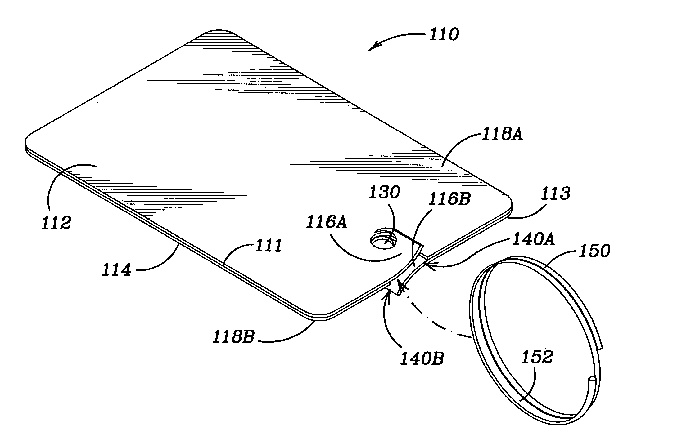
[0022]In a preferred embodiment of the invention the card is substantially rectangular, the aperture is circular, the slot is significantly narrower than the width of the aperture and the card retaining member, the slot is aligned along a tangent to the aperture or at a point the card retaining member is least likely to pull against the aperture and with the slot continuing in a substantially curved manner away from the aperture to one of the edges of the card. The path of the slot forms a retaining “hook” with the greatest amount of card material to resist the card retaining member pulling through the card in the directions the retaining member is most likely to pull. The more circuitous the path of the slot, the more the card material must be deformed to intentionally release the card from the card retaining member. The preferred embodiment of the card retaining member is a substantially circular ring made of a rigid material, such as metal. Use of, the invention in this preferred embodiment requires a simultaneous application of force to the card while moving the card retaining member in a constantly changing direction relative to the card aperture to cause the card retaining member to be removed from the card aperture, thereby minimizing the risk of the card detaching from the card retaining member due to an unintended or accidental application of force. The preferred embodiment also locates the aperture a sufficient distance from any edge of the card to ensure a sufficient amount of card material between any point along the aperture and any card edge to minimize the potential for breakage of the card during ordinary and intended use.
[0025]An alternative use for the invention includes its use for lock-out / tag-out cards. These cards are typically made of a heavy grade paper or a plastic material, and are used with industrial equipment to alert users to an atypical operational status of that equipment. For example, when a piece of equipment is to be cleaned, it typically should not also be operating, for both the safety of the person performing the cleaning and also to ensure proper access to its components. The operational control of that piece of equipment should therefore have some sort of indicator to alert potential operators that cleaning is occurring, and that the equipment should not be operating. The lock-out component is typically a mechanical device of some sort to physically prevent activation of the operational controller, and the tag-out component is typically a card with some sort of warning label. Tag-out cards found in the prior art typically are attached to the appropriate component by string, twine, wire, and the like, making it inconvenient to attach and detach and potentially providing a disincentive to the use of such tags. Applying the present invention to tag-out cards will improve the ease of use of the tags, while ensuring the security of the attachment of the tags.
[0026]Another alternative use of the invention is its application to temporary magnetic strip keys or entry cards. Cutting the aperture and slot into an entry card enables conveniently retaining it on a user's key chain or neck lanyard.
[0027]Another alternative use for the invention is for the organization of business cards. Business cards are typically constructed of a heavy grade paper that will accommodate an aperture and slot being cut into them. The card retaining member serves to keep business cards together, yet allows easy removal of a card for reference or for distribution.

Problems solved by technology

However, cards fall out of wallets, and sometimes people forget to return the card to their wallet or purse.
Thus, loss of such cards is a common event, and the inconvenience due to the loss of a credit card can be considerable.
Loss of the card may mean that access to funds is no longer possible until the card is recovered or replaced, this possibly taking days or even weeks.
However, it is usually quite difficult for an individual to attach a card to a key ring or easily remove it to pass through a card reader.
The securement means of the Schaeffer patent is limited to use with only one a single card, thereby, leaving a need for a retaining member that can be used with and hold a plurality of information-bearing cards.
However, the description of a hole for attaching the data card to a key chain still requires the opening and re-closing of the key chain, a cumbersome task to be associated with the reduced size card.
Additionally, the Pentz disclosure does not contemplate an aperture associated with a channel that would easily permit the passage of a card-retaining member, e.g., a key chain or retaining ring, from the edge of the card to the aperture without the need to open, or thread the retaining device through the hole, and then re-close the device for secure attachment.
The key holder of Kasprzycki is formed as an elongated slot in a corner of the key holder and does not contemplate use with a data or credit card; the device is limited to use with hotel keys.
While this configuration achieves the above-stated goal, it requires a specially designed card and thus is not adaptable to standard credit cards.
However, like the Schaeffer device, the safety hook of Romberger requires not only a specially designed and sized card, but also does not attach by means of any mechanism associated with the card.
This configuration allows for a single card to be easily attached to and detached from a shirt button, but is not amenable to retaining multiple cards on a single retention device.
Moreover, the slit is cut such that, when the card is attached to a shirt button, a downward force on the card will easily cause detachment, leading to a risk of inadvertent detachment.
None of the disclosed inventions meet the requirements of providing an easy means for attaching and detaching a standard credit card to and from a card retaining member, while minimizing the risk of inadvertent detachment.

Method used


Image

  • Removably attachable card and card retaining device
  • Removably attachable card and card retaining device
  • Removably attachable card and card retaining device

Examples


Embodiment Construction

[0055]The following detailed description is of the best presently contemplated mode of carrying out the invention. The description is not intended in a limiting sense, and is made solely for the purpose of illustrating the general principles of the invention. The various features and advantages of the present invention may be more readily understood with reference to the following detailed description taken in conjunction with the accompanying drawings.

[0056]Referring now to the drawings in detail, where like numerals refer to like parts or elements, there is shown an improved information-bearing card 10 and card retaining member 50 for removably securing the card to the card retaining member along with the primary elements of the present invention. The invention requires the card 10 to be configured with an aperture 30 and a slot 40, with the aperture 30 being located within the body of the card and the slot 40 running from the aperture 30 to an edge of the card. Further structural...


PUM


Abstract

An improved combination card and card retaining member for removably securing the card to the card retaining member, the card having formed within it an aperture and a slot connecting the aperture with an edge of the card, and the card retaining member being a member, such as a ring, which may be passed through the slot and into the aperture to secure the card to the card retaining member. The aperture and slot are configured and located on the card in such a manner as to improve the ease of attachment and detachment of the card to and from the card retaining member while minimizing the risk of accidental detachment of the card from the card retaining member. One or more cards may be used simultaneously with a single card retaining member. A preferred use of the invention is to retain and organize credit cards.

Description

BACKGROUND OF THE INVENTION[0001]The present invention relates generally to the field of information-bearing cards, and particularly to means and methods for securely attaching information-bearing cards to card-retaining members. The improved information-bearing cards and card retaining members provide for any card to be easily secured to the card retaining member and easily detached therefrom as well, while reducing the incidence of accidental detachment of the card from the card retaining member.[0002]Information-bearing cards are commonly found today. Examples of information bearing cards include credit cards bearing information such as cardholder name, account number, and bank name; and hotel room access cards bearing information such as a room or door lock pass code. This information is incorporated into the card as embossed alphanumeric characters, as information recorded on a magnetic strip, as a hologram, and / or as printed information. An information-bearing card can also in...

Claims


Application Information

Patent Timeline
Patent Type & Authority Applications(United States)
IPC IPC(8): G09F3/08
CPCG09F3/20
Inventor GOETTING, THOMAS J.
Owner GOETTING THOMAS J
Learn More