
Hand-held power tool with torque limiter

Inactive Publication Date: 2009-01-22
ROBERT BOSCH GMBH
View PDF19 Cites 11 Cited by
  • Summary
  • Abstract
  • Description
  • Claims
  • Application Information

AI Technical Summary

Benefits of technology

[0015]In a further feature of the invention, the torque limiter includes an adjusting element with a control cam, which has a first segment for adjusting the maximum torque and a second segment, different in its control action from the first, for adjusting a drilling mode without adjustable torque limitation. The second segment of the control cam can for instance be embodied more steeply than the first, so that with a brief actuation of the adjusting element, a major change in the torque, from a maximum torque to a spanning position or to the overload torque, can be achieved. It is also possible to design the second segment as very low or without a change in torque, so that the adjusting element can be prevented from being forced out of the drilling mode setting unintentionally.
[0015]In a further feature of the invention, the torque limiter includes an adjusting element with a control cam, which has a first segment for adjusting the maximum torque and a second segment, different in its control action from the first, for adjusting a drilling mode without adjustable torque limitation. The second segment of the control cam can for instance be embodied more steeply than the first, so that with a brief actuation of the adjusting element, a major change in the torque, from a maximum torque to a spanning position or to the overload torque, can be achieved. It is also possible to design the second segment as very low or without a change in torque, so that the adjusting element can be prevented from being forced out of the drilling mode setting unintentionally.
[0010]Another favorable feature with regard to compactness of the hand-held power tool is the use of an element which is an element of both the torque limiter and of the overhead coupling. Moreover, additional elements can be dispensed with, keeping the hand-held power tool inexpensive. The element is expediently an element such that at it, the flow of force from the motor power takeoff to the tool driver is interrupted by the torque limiter or the overhead coupling, and in particular by both the torque limiter and the overhead coupling.

Problems solved by technology

Hand-held power tools, such as rechargeable-battery-operated screwdrivers, rechargeable-battery-operated power drills, or rechargeable-battery-operated percussion power drills, have a high drive torque, whose limitation is desirable for some applications.

Method used


Image

  • Hand-held power tool with torque limiter
  • Hand-held power tool with torque limiter
  • Hand-held power tool with torque limiter

Examples


Embodiment Construction

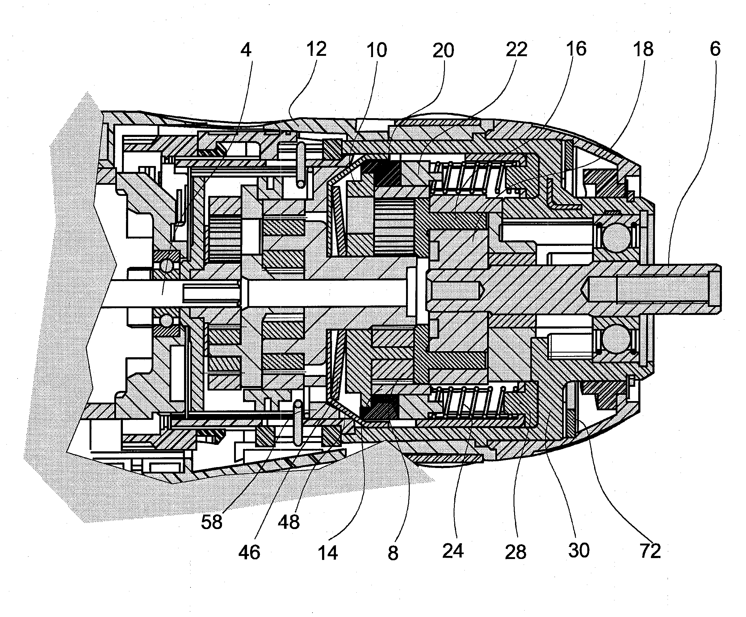
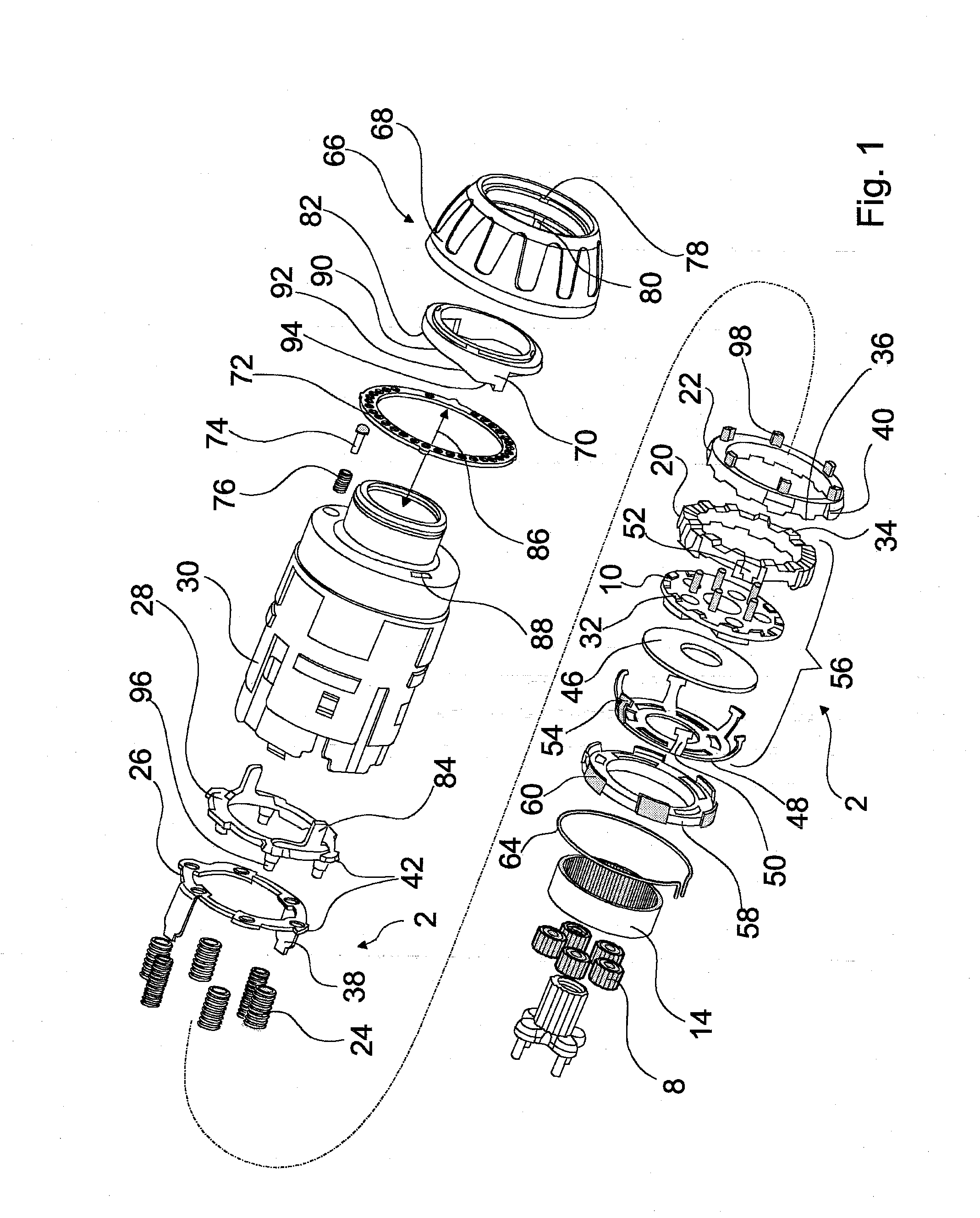
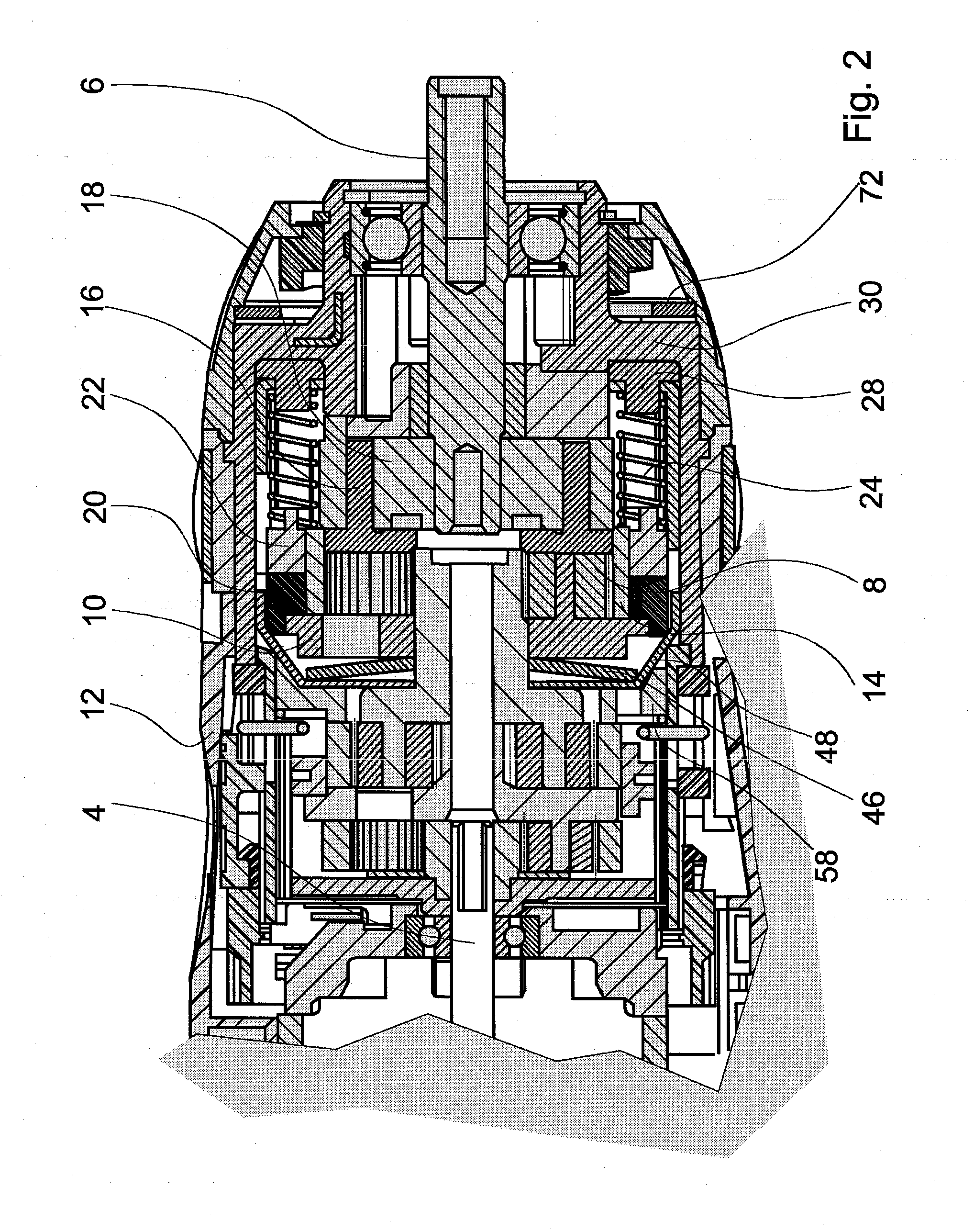
[0023]FIGS. 1 and 2 show a front part of a hand-held power tool, designed as a rechargeable-battery-operated screwdriver, in an exploded view (FIG. 1) and a sectional view (FIG. 2). The hand-held power tool includes a torque limiter 2, a motor power takeoff 4, and a tool driver 6. For driving the tool driver 6, a torque is transmitted from the motor power takeoff 4 to a three-stage planetary gear, with among other elements planet wheels 8, which consequently rotate about their own axis. The planet wheels 8 are supported on a planet carrier 10, which in the normal operating mode does not rotate with them or in other words is connected in stationary fashion to a housing 12 of the hand-held power tool. The planet wheels 8 drive a ring gear 14, whose internal toothing engages a slaving means 16 circumferentially and drives it. The slaving means 16 drives a star 18, and the star drives the tool driver 6 via a square socket.

[0024]In normal operation, the planet carrier 10 rests in station...


PUM


Abstract

The invention relates to a hand tool machine with a torque limiter (2) enabling a user to set a maximum torque which is transmitted by a motor drive (4) to a tool carrier (6). According to the invention, the hand tool machine comprises an overload clutch which interrupts a power flux between the motor drive (4) and the tool carrier (6) when the transmitted torque exceeds the overload torque.

Description

PRIOR ART[0001]The invention is based on a hand-held power tool having a torque limiter as generically defined by the preamble to claim 1.[0002]Hand-held power tools, such as rechargeable-battery-operated screwdrivers, rechargeable-battery-operated power drills, or rechargeable-battery-operated percussion power drills, have a high drive torque, whose limitation is desirable for some applications. By means of an adjustable torque limitation, a number of screws can for instance be screwed into a workpiece with the same screwing-in torque, and a torque limiter unlatches as soon as the screws present a certain torque resistance to a motor power takeoff. For adapting the maximum torque to the task to be performed, the torque limiter is adjustable by a user.[0003]From German Patent Disclosure DE 103 09 057 A1, a hand-held power tool with a torque limitation as described above is known. The maximum torque that is to be transmitted to the tool driver is adjusted by a user, and a torque limi...

Claims


Application Information

Patent Timeline
IPC IPC(8): B23Q5/54
CPCB25B21/00B25B23/141B25B23/14
Inventor AEBERHARD, BRUNO
Owner ROBERT BOSCH GMBH
Learn More