Optical detection apparatus, optical detection method, and microfluidic system including the optical detection apparatus

a technology of optical detection apparatus and microfluidic system, which is applied in the direction of instruments, measurement devices, color/spectral properties measurements, etc., can solve the problems of long detection time, high price of optical components, and high cost of optical components, so as to reduce manufacturing costs and reduce time , the effect of protecting the lives of urgent patients

Active Publication Date: 2009-01-22
PRECISIONBIOSENSOR INC
View PDF9 Cites 30 Cited by
  • Summary
  • Abstract
  • Description
  • Claims
  • Application Information

AI Technical Summary

Benefits of technology

[0025]After the measuring, absorbance of the detection chamber is calculated and a concentration of a specific components contained in the sample is determined on the basis of the absorbance According to the present invention, the manufacturing costs can be reduced because there is no need to use expensive optical components, such as a filter wheel. In addition, when various kinds of reactions are performed using a sample, the results can be obtained immediately. Accordingly, examinations for diagnosis and treatment of a patent can be performed in a reduced time, and especially, lives of urgent patients can be protected and their medical states can be improved.

Problems solved by technology

However, such optical detection apparatuses require expensive optical components and thus the price thereof is high.
In addition, a long time is required to detect results of various processes which are performed using the disk-type microfluidic apparatus.

Method used


Image

  • Optical detection apparatus, optical detection method, and microfluidic system including the optical detection apparatus
  • Optical detection apparatus, optical detection method, and microfluidic system including the optical detection apparatus
  • Optical detection apparatus, optical detection method, and microfluidic system including the optical detection apparatus

Examples


Embodiment Construction

[0031]The present invention will now be described more fully with reference to the accompanying drawings, in which exemplary embodiments of the invention are shown.

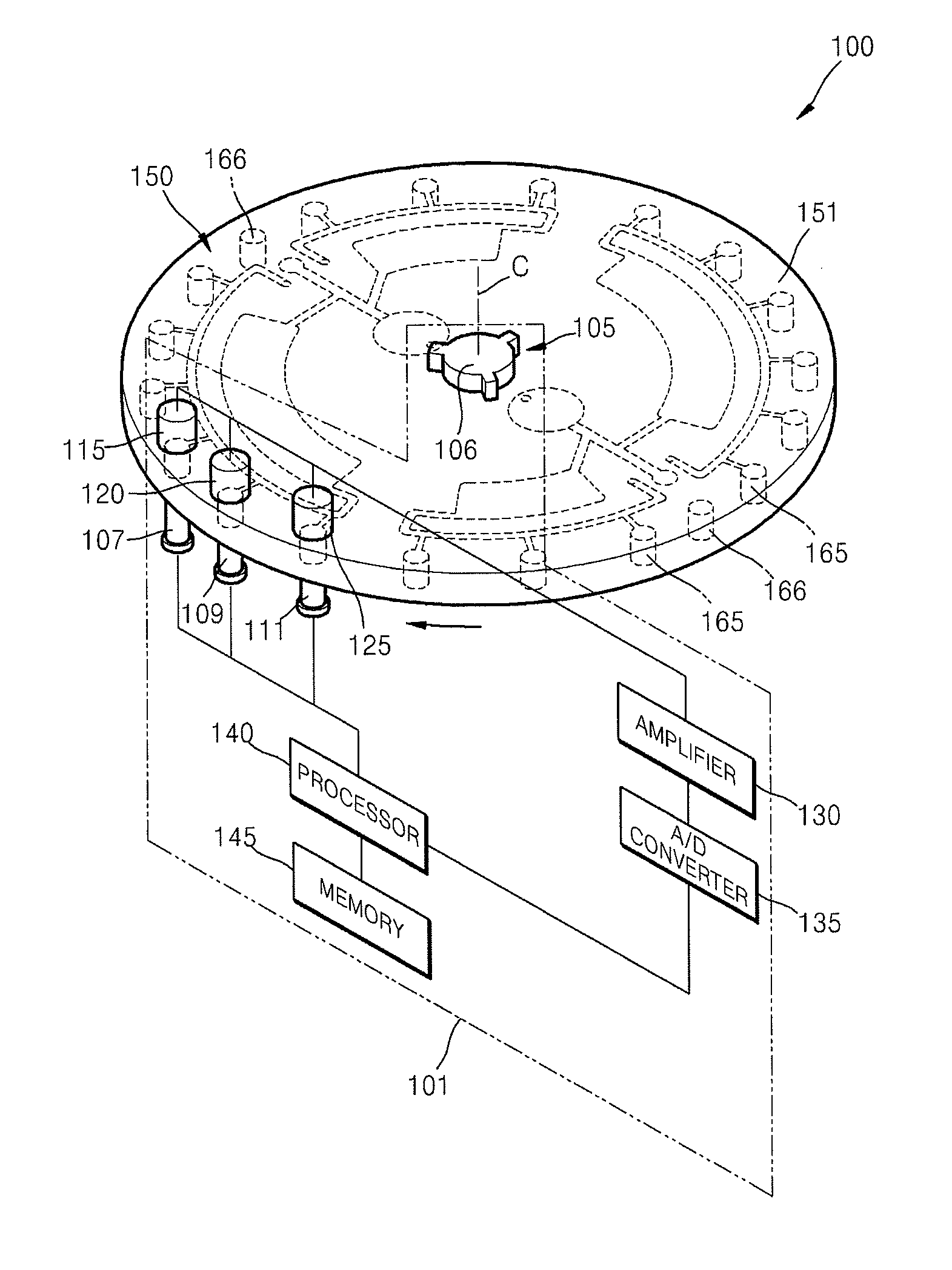
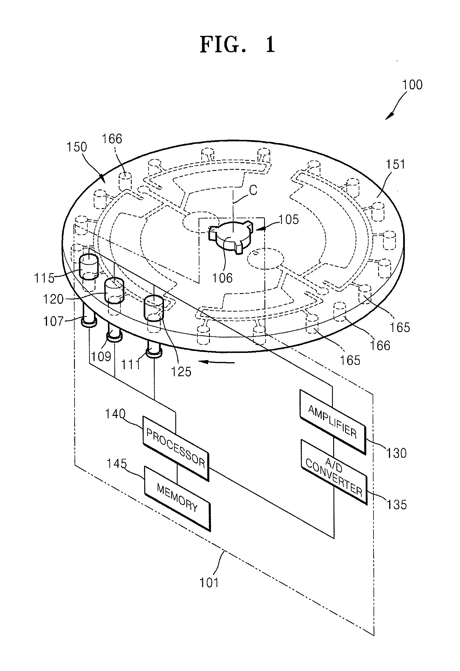
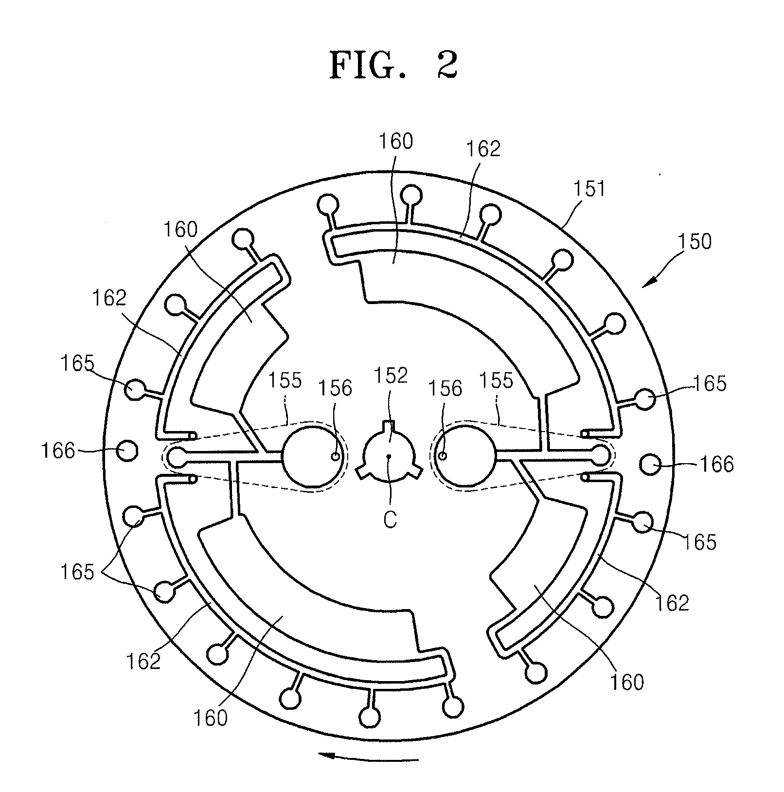
[0032]FIG. 1 is a perspective view of a microfluidic system 100 according to an embodiment of the present invention, and FIG. 2 is a plan view of a disk-type microfluidic apparatus 150 of the microfluidic system of FIG. 1.

[0033]Referring to FIG. 1, the microfluidic system 100 includes the disk-type microfluidic apparatus 150, and an optical detection apparatus 101 which optically measures properties of a sample contained in a detection chamber 165 of the disk-type microfluidic apparatus 150. The disk-type microfluidic apparatus 150 includes structures for the centrifugal separation, distribution, and biochemical reactions of a sample on a disk-like platform 151.

[0034]The disk-type platform 151 can be made of a plastic material that is easily handled to obtain a desired shape, optically transparent, and biologically inacti...


PUM

PropertyMeasurementUnit
wavelength bandaaaaaaaaaa

Abstract

Provided are an optical detection apparatus, a microfluidic system including the same, and an optical detection method. The optical detection apparatus including: at least one light emission unit which emits light of a predetermined wavelength band; at least one light receiving unit which is disposed such that the light receiving unit receives the light emitted from the light emission unit and generates an electrical signal according to the intensity of the light received, wherein the number of light receiving units is the same as the number of light emission units; a rotation operating unit which rotates a disk-type microfluidic apparatus comprising at least one detection chamber in which a sample is to be loaded such that the detection chamber is disposed in a light pathway between the light emission unit and the light receiving unit; and a processor which measures a property of the sample contained in the detection chamber using the electrical signal generated by the light receiving unit.

Description

CROSS-REFERENCE TO RELATED PATENT APPLICATIONS[0001]This application claims the benefit of Korean Patent Application No. 10-2007-0073116, filed on Jul. 20, 2007, in the Korean Intellectual Property Office, the disclosure of which is incorporated herein in its entirety by reference.BACKGROUND OF THE INVENTION[0002]1. Field of the Invention[0003]The present invention relates to an optical detection apparatus for detecting the concentration of a specific component in a biochemical sample using an optical method, an optical detection method, and a microfluidic system including the optical detection apparatus.[0004]2. Description of the Related Art[0005]In the field of microfluidics, conventionally, a microfluidic apparatus which is used in processes using a small amount of a fluid includes a chamber which stores a small amount of a fluid, a channel through which the fluid flows, and a valve which controls the flow of the fluid. A bio-chip is an apparatus in which an assay including a bi...

Claims


Application Information

Patent Timeline
Patent Type & Authority Applications(United States)
IPC IPC(8): G01N21/00
CPCG01N21/07G01N21/314G01N21/276G01N21/253G01N15/00G01N21/00
Inventor KIM, SU-HYEONLEE, JEONG-GUN
Owner PRECISIONBIOSENSOR INC
Why Eureka
Try Eureka