

Light scanning apparatus and scanning display apparatus
a technology of light scanning apparatus and display apparatus, which is applied in the direction of instruments, lenses, optical elements, etc., can solve the problems of image sharpness degradation, and achieve the effect of reducing speckle noise without deteriorating resolution
- Summary
- Abstract
- Description
- Claims
- Application Information
AI Technical Summary
Benefits of technology
Problems solved by technology
Method used
Image

Examples
embodiment 1
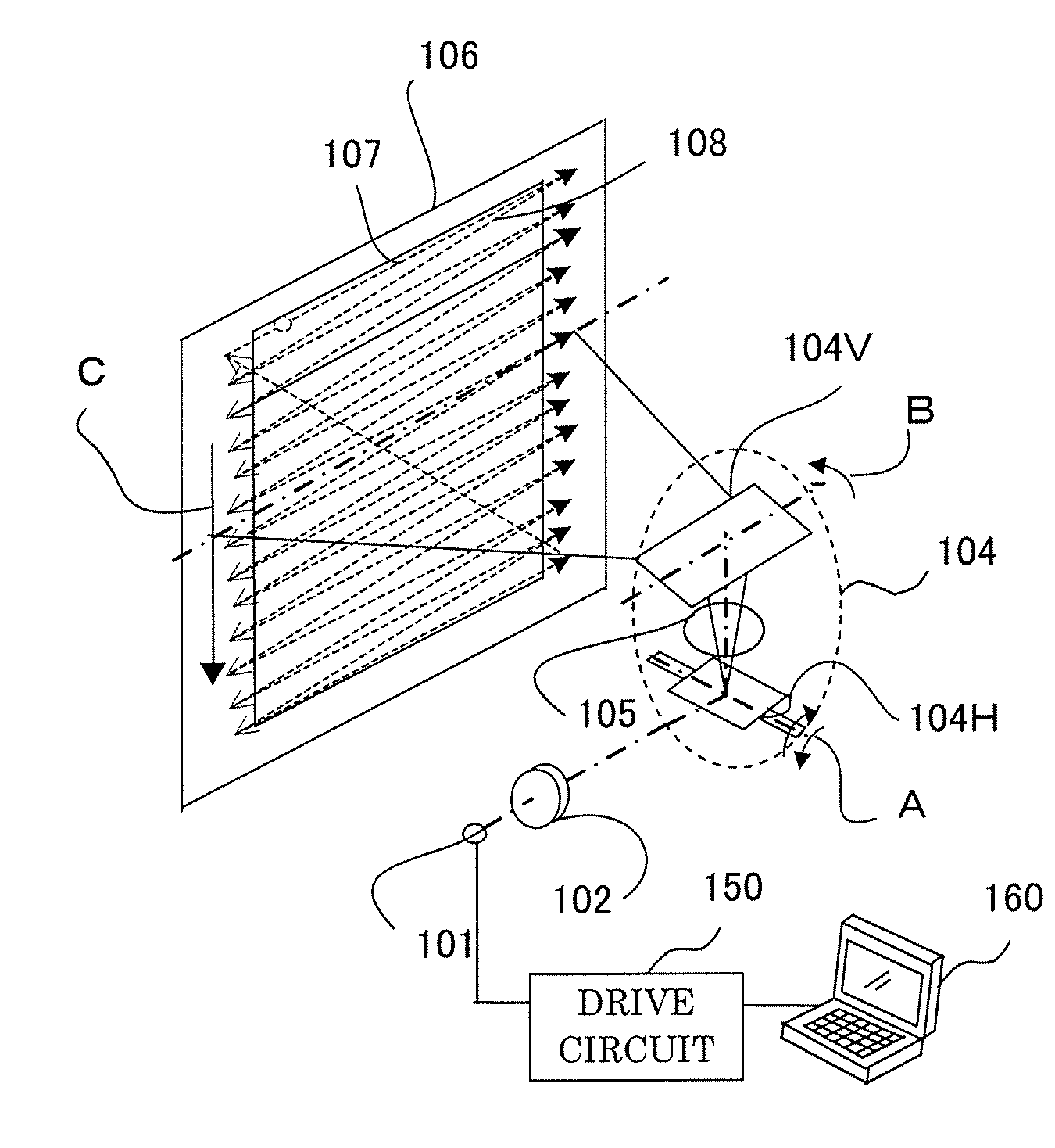
[0033]FIG. 1 schematically shows a configuration of a light scanning apparatus and a scanning display apparatus comprising the light scanning apparatus which are embodiment 1 of the present invention.
[0034]Reference numeral 101 denotes a laser light source, and 150 denotes a drive circuit driving the laser light source. The drive circuit 150 inputs image information from an image supply apparatus 160, such as personal computers, DVD players, and TV tuners. The drive circuit 150 modulation drives the laser light source 101 in accordance with the inputted image information. This is similar in the embodiment to be mentioned later.
[0035]The emitted coherent laser light beam (laser light beam having coherence) from the laser light source 101 is a divergent light beam, and the divergent light beam is converted into a collimated light beam by a collimator lens 102. It is desirable for the light beam emitting from the laser light source to be a light beam with high coherence (coherent light...
embodiment 2
[0105]The configuration explained with above embodiment 1 (and illustrated by other embodiments to be mentioned later) can be applied when using a light source which emits the three colors of RGB. In other words, a light scanning apparatus and a scanning display apparatus which project a color image can be configured by applying the configuration shown in embodiment 1.
[0106]FIG. 7 shows an example of a color light source unit used in the apparatus of the present embodiment. A color light source unit 701, for example includes three laser light sources which are a red semiconductor laser 701a with an emission wavelength of 640 nm, a green laser light source 701b with an emission wavelength of 532 nm, and blue semiconductor laser 701c with an emission wavelength of 440 nm. Further, the SHG light source which generates a green laser due to a wavelength conversion from an infrared laser may be used as the green laser light source 701b.
[0107]Light beams emitted from laser light sources 7...
embodiment 3
[0109]FIG. 8 shows a horizontal section of the light scanning apparatus (and the scanning display apparatus) which is embodiment 3 of the present invention.
[0110]The present embodiment differs from embodiment 1 in that the two-dimensional scanning device capable of scanning a light beam two dimensionally with one is used as a scanner, and the pitch of the microlens in the microlens array as the light beam component generator is set at 20 μm.
[0111]The coherent light beam (laser light beam or divergent light beam) emitted from a laser light source 801 is converted into a collimated light beam by the collimator lens 802 and then the width of the light beam is limited by aperture stop 803, and then it enters a two-dimensional scanning device 804.
[0112]The deflected light beam deflected in the horizontal direction and the vertical direction by the two-dimensional scanning device 804 is imaged on the screen 806 as a spot by an image-forming optical system 805 configured from a scanning op...
PUM
 Abstract
Description
Claims
Application Information