Computer program using particle method

a particle method and computer program technology, applied in the field of computer program for particle methods, can solve the problems of difficult to take into account the complex modes of using, fundamentally unsuitable for a dispersed system, and limited particle shape in spheres or no shape, and achieve the effect of large deformation of each particl

Inactive Publication Date: 2009-01-22
HORI AKIO +1
View PDF3 Cites 9 Cited by
  • Summary
  • Abstract
  • Description
  • Claims
  • Application Information

AI Technical Summary

Benefits of technology

[0011]It is an object of the present invention to provide a numerical analytical method for a dispersed system in which contact and detachment are repeated and make FEM unsuitable. It is another object of the present invention to provide an accurate contact model between the particles with a smooth surface unlimited to sphere, and provide an analytical method for a more complicated shaped problem with less number of particles. It is still another object of the present invention to allow analytical coexistence of the particles and the finite elements that are for a continuum portion, and also to allow large deformation of each particle.

Problems solved by technology

However, FEM using the treatment is fundamentally unsuitable for a dispersed system, because FEM is naturally for the continuum and treats partial contact between discontinued elements.
Therefore, it is difficult to take account of these complex modes using FEM.
However, the particle shape is limited in sphere or no shape at present (for example, “Particle method”, S. Koshizuka, 2005, Maruzen, Tokyo, in Japanese).
Therefore, there is a problem of requiring a large number of particles in modeling of a complicated shape using the particle method particularly in three dimensions (3D).
Moreover, even if a large number of particles are used, there is a problem in that microscopic shape of the particles is remained and decides microscopically the contacting direction between assemblies of the particles.
However, the mesh-free method is based on the continuum and difficult to apply to a strongly nonlinear problem or shape changes.

Method used


Image

  • Computer program using particle method
  • Computer program using particle method
  • Computer program using particle method

Examples


Embodiment Construction

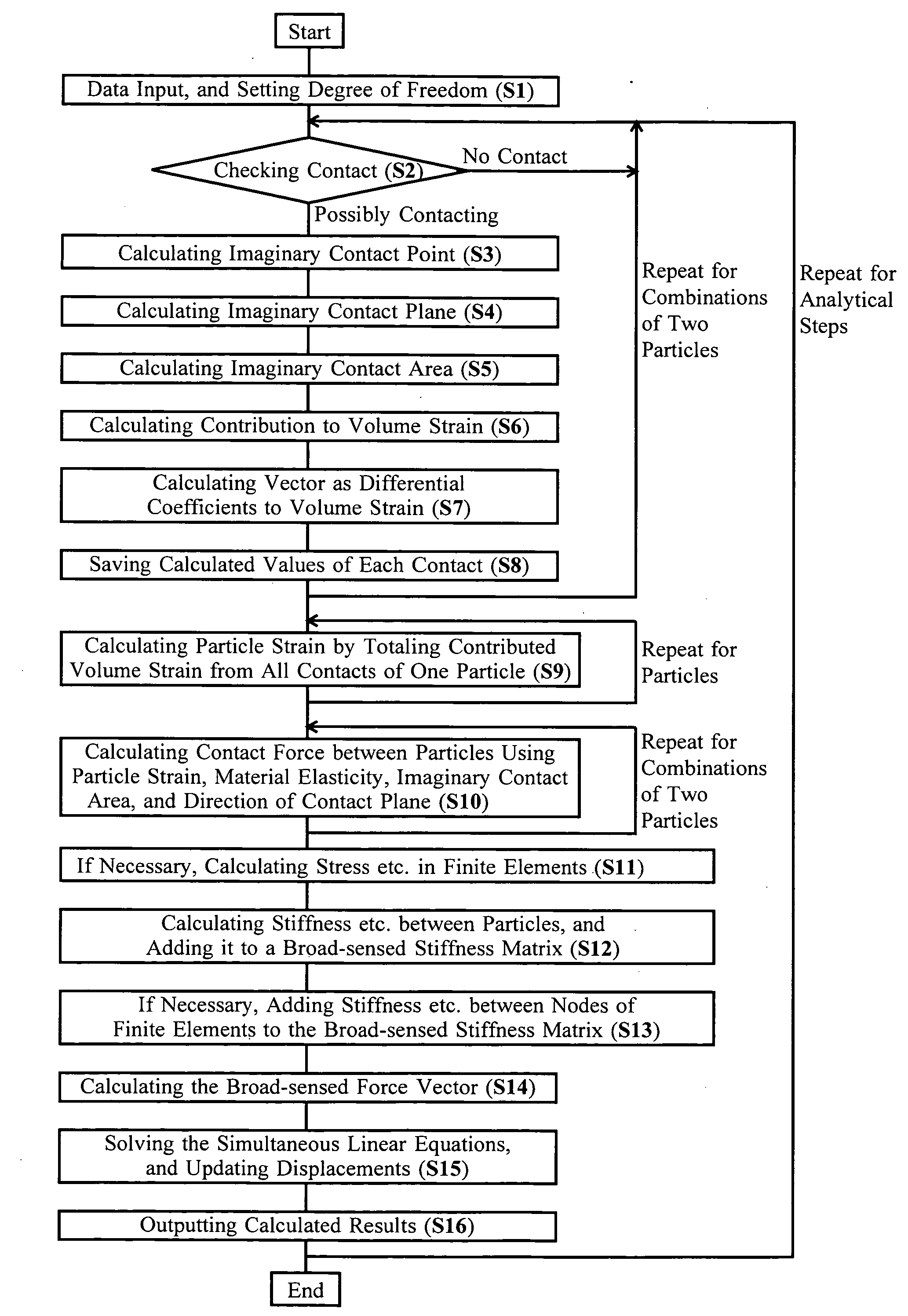
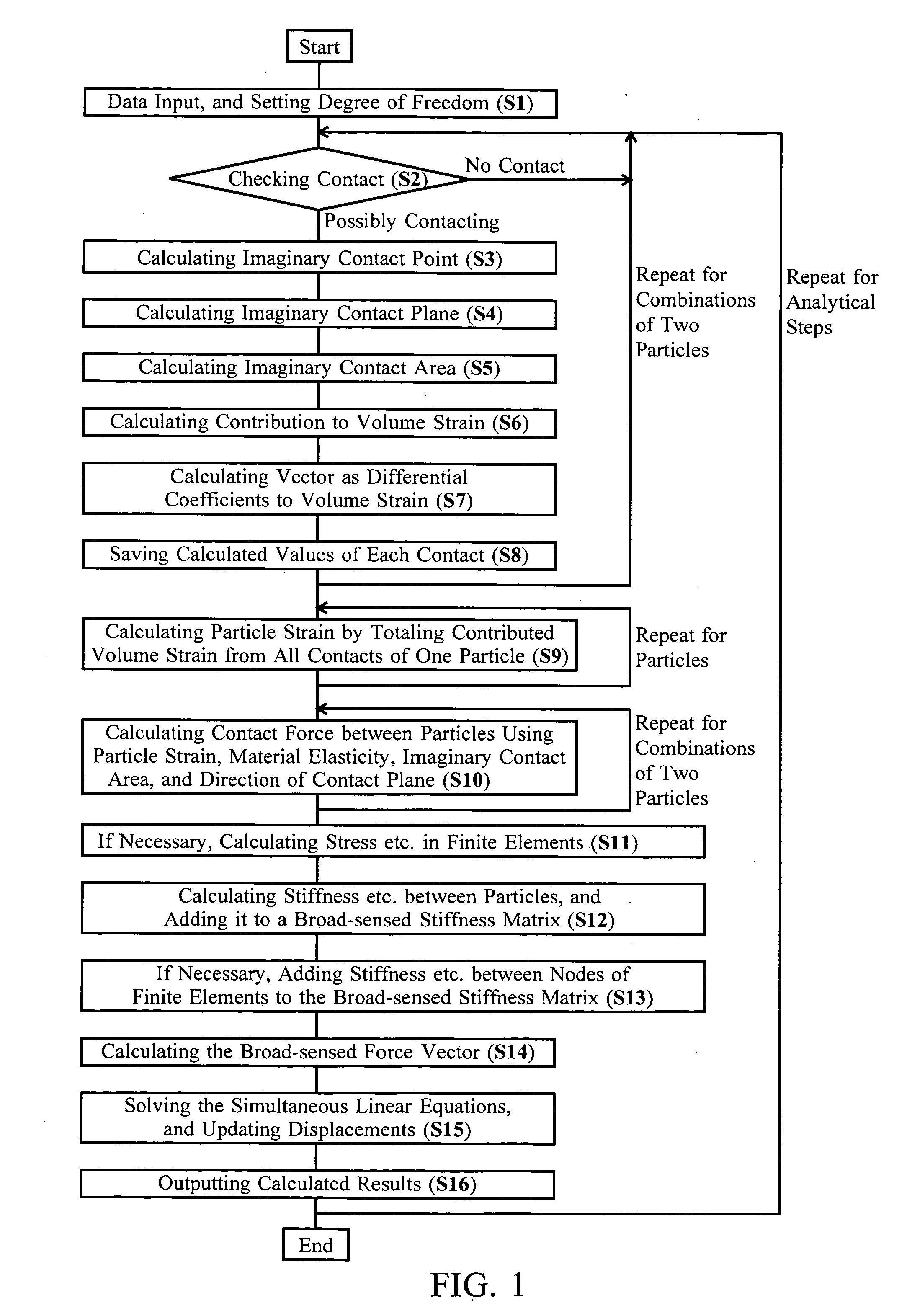
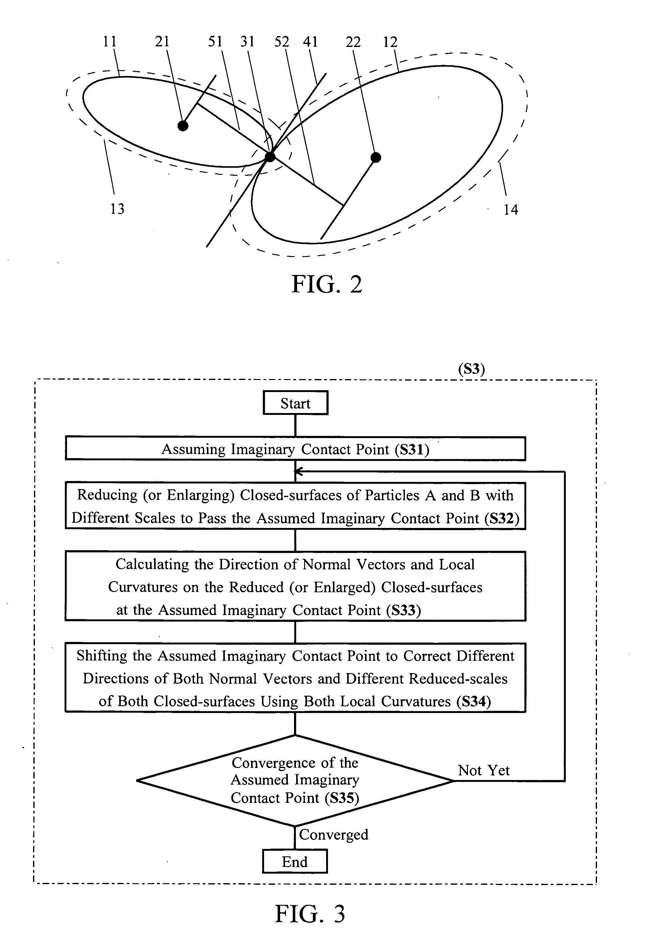
[0023]The invention enables unlimited particle shapes not only to be a sphere in the particle method. First, the invention includes setting a mathematically-smooth (and usually closed) surface for each particle shape and size, and judging existence of contact between two particles as that between two mathematically-smooth surfaces. Contact of two mathematically-smooth surfaces will be basically limited at one point under a very high probability and simplifies the contact mode. Strictly, although two surfaces can contact rarely at two or more points, the usual contact at only one point is assumed for the invention. Moreover, the surfaces are usually closed surfaces; however some surfaces may be unclosed for modeling the boundary condition with particles, and may be closed inside out for analyzing internal contact to the surfaces.

[0024]Next, to calculate displacements of a non-sphere particle, it is required to determine a point of action of contact force between two particles. Theref...


PUM


Abstract

Finite element methods are unsuitable for a dispersed system. Particle methods suitable for a dispersed system are limited in the particle shapes only a sphere that requires many particles to model a complicated shape especially in 3D. Proposed procedures for a particle method are roughly as follows. 1): Judging the existence of the contact between particles as that between mathematically-smooth closed surfaces representing particle shape and size. 2): Assuming an imaginary contact point and an imaginary contact plane the same as when both closed surfaces are reduced with the same scale to touch at one point. 3): Calculating imaginary contact area and imaginary contact stiffness etc. using the above point and plane. Based on these procedures, particle shapes are not limited but smooth. Therefore, a more complicated shaped problem in a dispersed system can be analyzed with less number of particles. Additionally, combined use with finite elements is capable.

Description

CROSS-REFERENCE TO RELATED APPLICATIONS[0001]The present application claims the benefit of patent application number 2007-211,559, filed in Japan on Jul. 18, 2007, the subject matter of which is hereby incorporated herein by reference.FEDERALLY SPONSORED RESEARCH[0002]Not ApplicableSEQUENCE LISTING OR PROGRAM [0003]Not ApplicableBACKGROUND[0004]1. Field of the Invention[0005]The present invention relates to a computer program for the particle method in a broad sense, in which objects are modeled into (or using) particles whose displacements and / or deformations can be calculated, if necessary, considering transmission (or exchange) of force, heat or material between the touched particles.[0006]2. Description of Related Art[0007]In the finite element method (FEM), mainly physical relations between the elements are described as relations between the nodes by dividing the continuum into piecewise elements enclosed with the nodes. Therefore, analysis of a contact-involving problem using ...

Claims


Application Information

Patent Timeline
Patent Type & Authority Applications(United States)
IPC IPC(8): G06G7/58
CPCG06F2217/16G06F17/5009G06F30/20G06F2111/10
Inventor HORI, AKIOKOJO, HIROMI
Owner HORI AKIO
Why Eureka
Try Eureka