Method and system for generation of power using stirling engine principles

a technology of stirling engine and principle, applied in the field of application of stirling engine principle, can solve problems such as engine failur

Inactive Publication Date: 2009-01-29
SILVER GUY +1
View PDF19 Cites 14 Cited by
  • Summary
  • Abstract
  • Description
  • Claims
  • Application Information

AI Technical Summary

Benefits of technology

[0007]The present invention provides a method and a rotary engine based on Stirling engine principles. According to one embodiment of the present invention, the housing of the rotary engine rotates as a result of fluid flow between two zones of different temperatures within a chamber in the housing. The torque in the rotary motion of the housing, therefore, may be used to drive machinery (e.g., a generator) through an axle or a gear structure coupled externally to the housing. Under this arrangement, unlike the prior art, a rotary engine of the present invention is not susceptible to failure due to a leak in the sealing of the housing.
[0008]According to one embodiment of the present invention, the hot zone of the chamber is heated by energy from a heat source, and a cooling system maintains the cold zone at a lower temperature than the hot zone. The cooling fluid may be drawn from a stationary external reservoir of cooling fluid. In one embodiment, the rotary motion of the housing may be used to draw the cooling fluid. In that embodiment, the volume of cooling fluid drawn into the rotary engine depends on the angular speed of the rotary motion which, in turn, may be determined by power output of the rotary engine. A self-regulating cooling system may therefore be achieved. A structure used to reinforce the housing at the point where the external axle (or the external gear structure) is to be attached may include a threaded passage. In that embodiment, the rotating threaded passage forces the cooling fluid into the housing, through passages distributed around the cold zone (e.g., the insulation layer abutting the cold zone, the fluid guide structure or the area between the cold zone and the housing) so as to maintain the cold zone to within a desired temperature range.
[0009]A turbine in a heat engine according to the present invention may be located in any suitable location on the interior surface of the housing hot zone or the cold zone, but is coupled to the housing to provide the housing rotary motion and is not required to directly drive an axle or a gear structure to provide the output power of the rotary engine. The chamber of the rotary engine may be filled with a compressible working fluid (e.g., air). Fluid guides may be provided within the chamber for guiding the flow of the compressible working fluid in preferred directions and flow velocities to provide higher efficiency. The fluid guides may also provide structural or mechanical support for the chamber. Thus the heat engine design provides a method for adjusting working fluid temperature inside housing 101, by running fluid from a cooling source or a heating source through fluid guides to the hot zone, the cold zone or both. This also provides methods to adjust power output of the engine without changing heat source or heat sink.
[0010]In one embodiment, a one-way valve may be provided between the hot zone and the cold zone prevents a working fluid in the hot zone to backflow into the cold zone.
[0011]In another embodiment, a metal mesh is provided in the hot zone to increase efficiency of heat transfer from the heat source to the hot zone. A heat storage structure can also be provided to minimize the impact of a fluctuating heat source on the power output of the rotary engine during engine cycles or to provide a secondary heat source for the heat engine. A high specific heat capacity fluid or a heat storage fluid can be used in the heat storage structure. Heat storage may be used to equalize the energy production or output requirements during times of different energy demand.

Problems solved by technology

A seal failure leads to the failure of the engine.

Method used


Image

  • Method and system for generation of power using stirling engine principles
  • Method and system for generation of power using stirling engine principles
  • Method and system for generation of power using stirling engine principles

Examples


Embodiment Construction

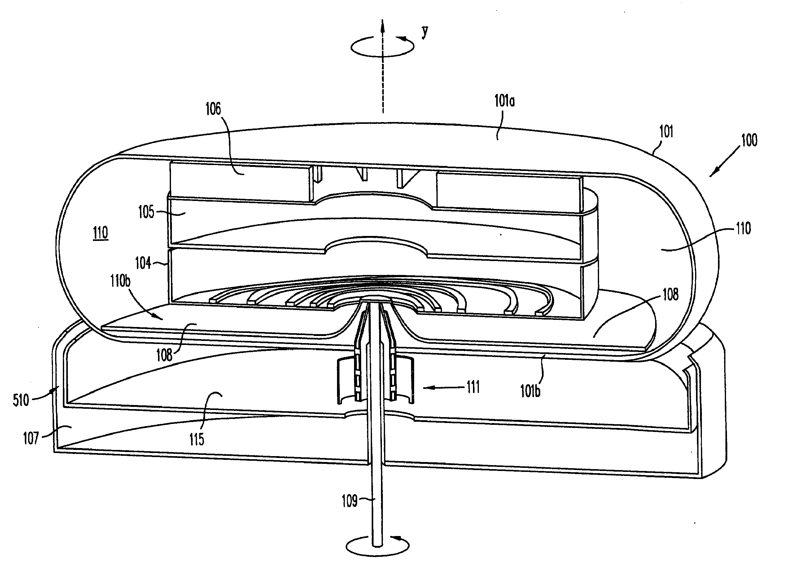
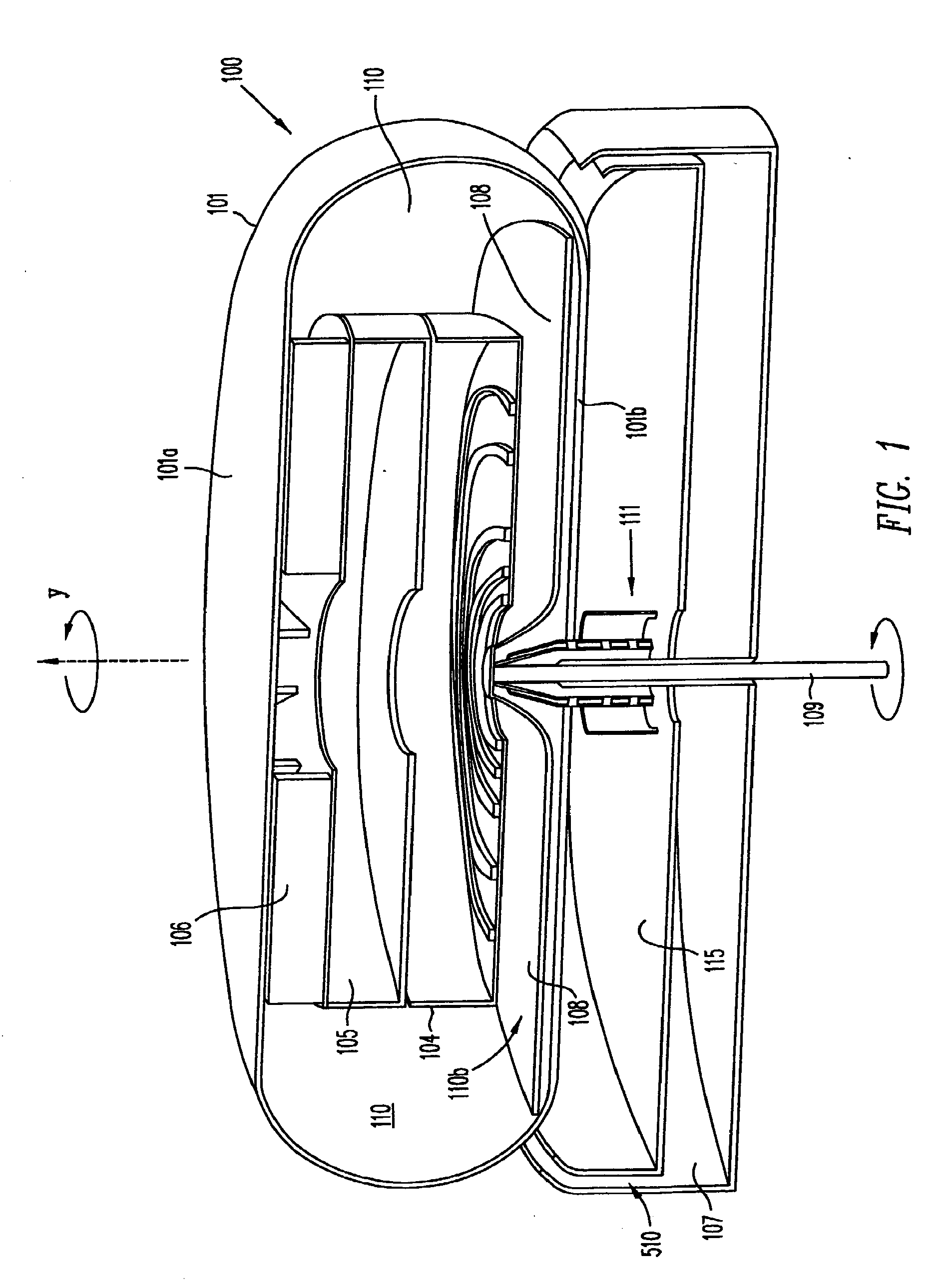
[0023]The present invention provides a heat engine that operates under Stirling engine principles to convert heat energy from a heat source into mechanical energy. The mechanical energy can be coupled to drive machinery and generators to perform useful work. Examples of a suitable heat source include solar, geothermal, fossil, landfill, recovered or other fuels.

[0024]FIG. 1 shows a cross section view of heat engine 100, including cooling fluid reservoir 107, according to one embodiment of the present invention. As shown in FIG. 1, heat engine 100 includes a chamber 110 enclosed in an enclosure or housing 101. During operation, when a heat source is provided incident on top surface 101a of housing 101, a temperature difference exists between a “hot zone”110a and a “cold zone”110b within chamber 110. The present invention exploits this temperature difference to cause housing 101 to rotate about the axis indicated by “Y” in a manner described below. Because the engine housing rotates d...


PUM


Abstract

A heat engine enclosing a chamber in housing has two zones maintained at different temperatures. The first zone receives heat energy from an external power source. The second zone is connected to the hot zone by two conduits, such that a fluid (e.g., air, water, or any other gas or liquid) filling the chamber can circulate between the two zones. The expansion of the fluid in the hot zone and the compression of the fluid in the cold zone drive the rotation of the housing to provide a power output. The fluid may be pressurized to enhance efficiency. A cooling fluid provided in a stationary reservoir maintains a preferred operating temperature difference between the hot zone and the cold zone. A heat storage structure containing a fluid with a high heat capacity may be provided as a heat reservoir.

Description

CROSS REFERENCE TO RELATED APPLICATIONS[0001]The present application is a continuation-in-part application of, and claims priority to, co-pending U.S. patent application Ser. No. 10 / 963,274, entitled “Method and System for Generation of Electrical and Mechanical Power using Stirling Engine Principles,” filed on Oct. 12, 2004, bearing Attorney Docket No. M-15504 US. The Co-pending patent application is hereby incorporated by reference in its entirety.BACKGROUND OF THE INVENTION[0002]1. Field of the Invention[0003]The present invention relates to applying Stirling engine principles to power conversion equipment design and use. In particular, the present invention relates to applying Stirling engine principles for power generation, such as generating mechanical power.[0004]2. Discussion of the Related Art[0005]The Stirling engine is a heat engine that operates by converting the heat energy which flows between zones of different temperatures into useful work. A typical Stirling engine u...

Claims


Application Information

Patent Timeline
Patent Type & Authority Applications(United States)
IPC IPC(8): F02G1/043F01K3/00F01K25/00
CPCF01K3/02Y02E10/46F03G6/068F02C1/10
Inventor SILVER, GUYWU, JUINERONG
Owner SILVER GUY
Why Eureka
Try Eureka