Hydraulic Drive Vehicle with Cooling System

Inactive Publication Date: 2009-01-29
ISHII NORIHIRO +4
View PDF4 Cites 30 Cited by
  • Summary
  • Abstract
  • Description
  • Claims
  • Application Information

AI Technical Summary

Benefits of technology

[0007]A first object of the invention is to provide a hydraulic drive vehicle provided with a

Problems solved by technology

Since the hydraulic pump is disposed in the pump housing, heat caused by sliding pistons and compressing fluid can be insufficiently radiated from the hydraulic pump, and the heat is accumulated in the pump ho

Method used


Image

  • Hydraulic Drive Vehicle with Cooling System
  • Hydraulic Drive Vehicle with Cooling System
  • Hydraulic Drive Vehicle with Cooling System

Examples


Embodiment Construction

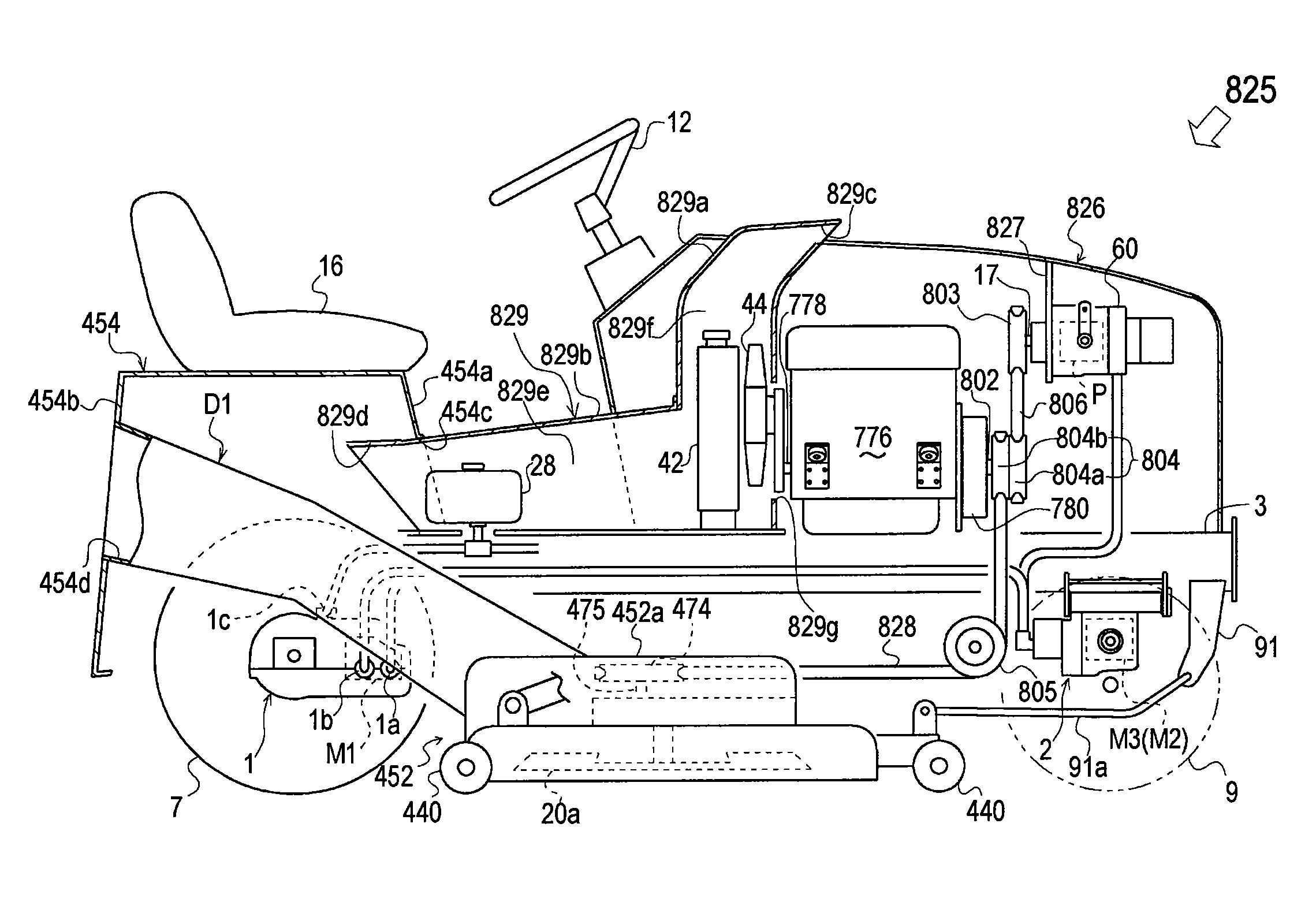
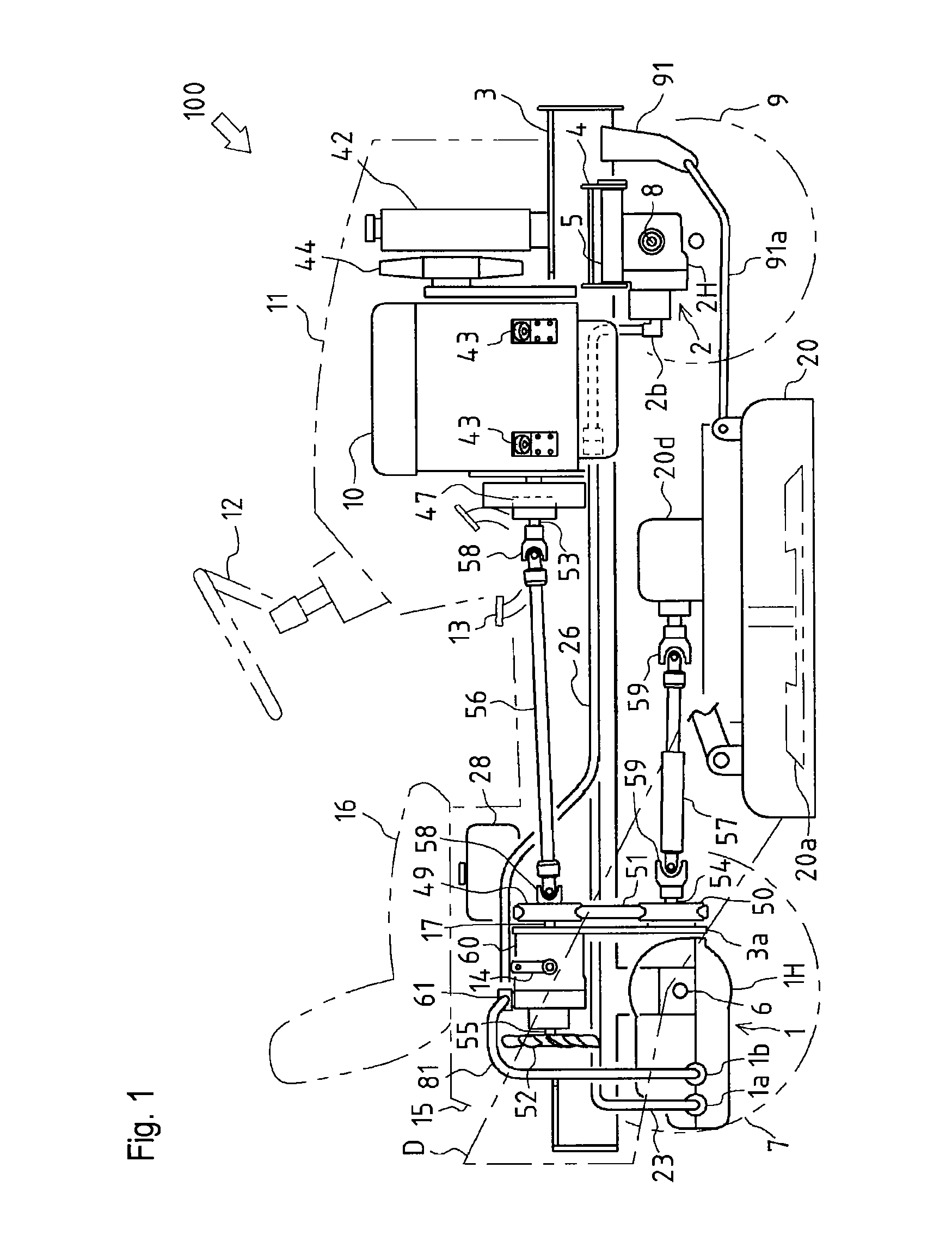
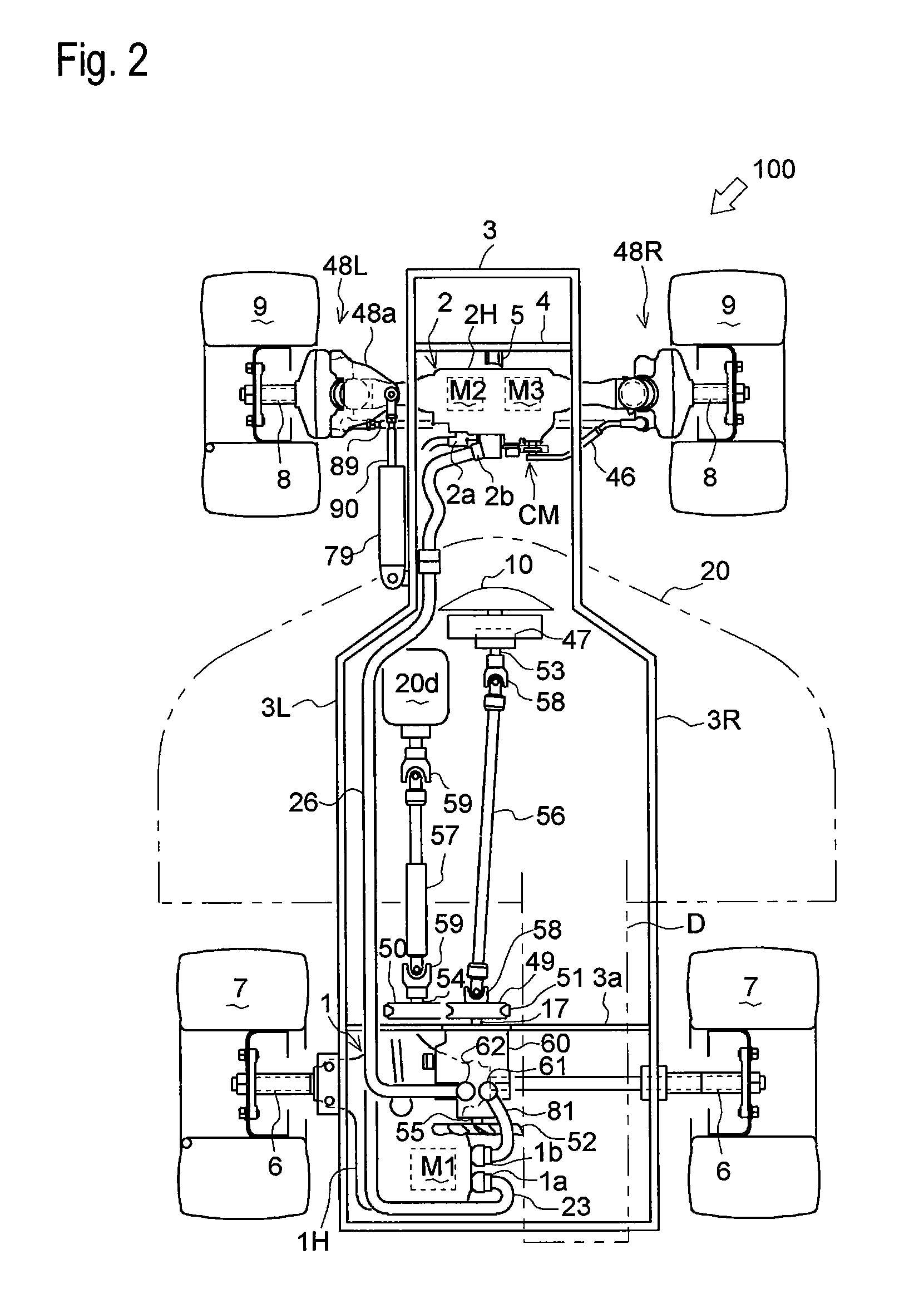
[0088]Referring to FIGS. 1 and 2, a hydraulic four-wheel drive working vehicle 100 equipped with a first power transmission system will be described. Vehicle 100 is an Ackerman type steered lawn tractor, comprising: a frame 3; a rear transaxle 1 supported by a rear portion of frame 3; a front transaxle 2 supported by a front portion of frame 3; an internal combustion engine 10, serving as a prime mover, supported by frame 3 between front and rear transaxles 1 and 2; a pump housing 60 supported by frame 3; and a mower 20 (an example of a working device driven by internal combustion engine 10) vertically movably suspended below frame 3. Frame 3 includes a pair of left and right vertical side plate portions 3L and 3R (as shown in FIG. 2) extended substantially in the fore-and-aft direction. Rear transaxle 1 and pump housing 60 are disposed in the inside space of frame 3 between the left and right side plate portions 3L and 3R.

[0089]In vehicle 100, pump housing 60 incorporating a variab...


PUM


Abstract

A hydraulic drive vehicle comprises a vehicle frame, a bonnet, a prime mover, a hydraulic transaxle, a seat, a reservoir tank, and a cooling fan and a cooling duct. The bonnet is supported on one of front and rear portions of the vehicle frame, and provided therein with a first space. The prime mover is disposed in the first space. The hydraulic transaxle is driven by the prime mover. The seat is supported on the other of the front and rear portions of the vehicle frame, and is provided therebelow with a second space. The reservoir tank is fluidly connected to the hydraulic transaxle. The cooling fan is driven by the prime mover. The cooling duct is disposed in the second space. The cooling fan and the reservoir tank are disposed in the cooling duct so that the cooling fan cools the reservoir tank. A hydraulic pump for driving the hydraulic transaxle is disposed in the cooling duct so as to be cooled by the cooling fan.

Description

CROSS REFERENCE TO RELATED APPLICATIONS[0001]This application is a continuation-in-part of U.S. patent application Ser. No. 11 / 433,551 filed May 15, 2006, which is hereby incorporated in its entirety by reference.BACKGROUND OF THE INVENTION[0002]1. Field of the Invention[0003]The invention relates to a cooling system of a hydraulically driven working vehicle, especially, for a large-size vehicle. Especially, the cooling system is provided for cooling a hydraulic pump for driving a hydraulic transaxle or for cooling a reservoir tank fluidly connected to the hydraulic pump or the hydraulic transaxle.[0004]2. Related Art[0005]Conventionally, there is a well-known hydraulically driven working vehicle, equipped with a hydraulic pump disposed in a housing and drivingly connected to a prime mover (internal combustion engine), and with a hydraulic motor disposed outside the housing and fluidly connected to the hydraulic pump so as to drive an axle. U.S. Pat. No. 6,732,828 discloses an examp...

Claims


Application Information

Patent Timeline
IPC IPC(8): B60K17/356B60K11/06
CPCA01D69/03B60K11/06B60K17/10B60K17/356F16H61/4165F15B2211/20546F15B2211/62F15B2211/7058F16D31/02B60Y2200/223
Inventor ISHII, NORIHIROIWAKI, KOJIISHINO, FUMITOSHIHASEGAWA, TOSHIYUKISHIMIZU, HIROAKI
Owner ISHII NORIHIRO
Why Eureka
Try Eureka