Caliper brake system

a brake system and caliper technology, applied in the direction of braking systems, fluid actuated brakes, transportation and packaging, etc., can solve the problems of high stress placed on the parking brake system and the motor, easy to forget, and dangerous situations may be created

Active Publication Date: 2009-01-29
LAMBERT BRAKE
View PDF17 Cites 18 Cited by
  • Summary
  • Abstract
  • Description
  • Claims
  • Application Information

AI Technical Summary

Benefits of technology

[0007]It is an object of another aspect of the present invention to provide a caliper brake system, as above, that provides a high braking force.
[0011]In accordance with another aspect of the present invention, a caliper brake system includes a housing having a first end and a second end, and a bore is provided within the housing. An end plug has a cylindrical body and an annular projecting rim positioned within the bore adjacent to the second end. A piston is slidably positioned within the bore, and a spring assembly is positioned between the piston and the cylindrical body of the end plug and circumferentially within the annular projecting rim. The spring assembly includes at least one spring stack having an exterior spring, an intermediate spring, and an inner spring positioned on a common central axis providing a biasing force on the piston in a direction toward said first end of said housing to activate the brake. A fluid chamber is defined by the bore and the piston, and at least one annular seal positioned between the piston and the bore to prevent leakage therefrom. A fluid supply network is adapted to provide pressurized fluid to the fluid chamber to selectively overcome the biasing force acting on the piston, thereby deactivating the brake.
[0012]In accordance with yet another aspect of the present invention, a caliper brake system adapted to engage the rotor of a vehicle includes a pair of stators adapted to be positioned on opposing sides of the rotor. A piston engages one of the stators and is positioned within a bore. A spring assembly provides a biasing force to cause the stators to engage the rotor. A fluid supply network provides pressurized fluid to a fluid chamber causing the piston to overcome the biasing force of the spring assembly and causing the stators to disengage the rotor permitting the rotor to rotate freely.

Problems solved by technology

While such manual activation or deactivation of the brake is not difficult or time consuming, it is often easy to forget.
In the first instance, where the parking brake is not engaged, a dangerous situation may be created because the vehicle is more likely to begin moving without an operator at the controls if the parking brake is not engaged.
In the second instance, where the parking brake remains engaged when an operator attempts to move the vehicle, a high amount of stress is placed both on the parking brake system and the motor.

Method used


Image

  • Caliper brake system
  • Caliper brake system
  • Caliper brake system

Examples


Embodiment Construction

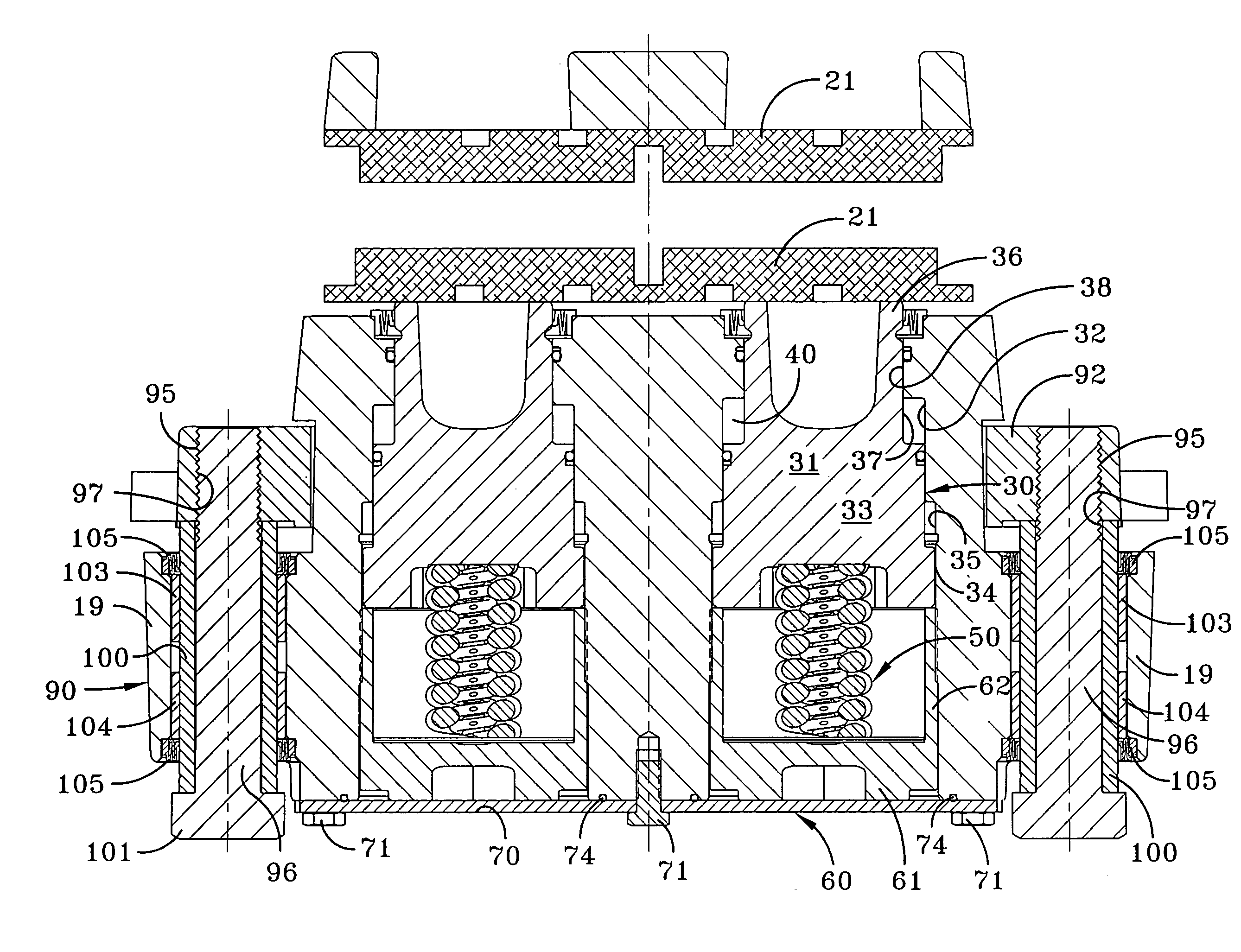
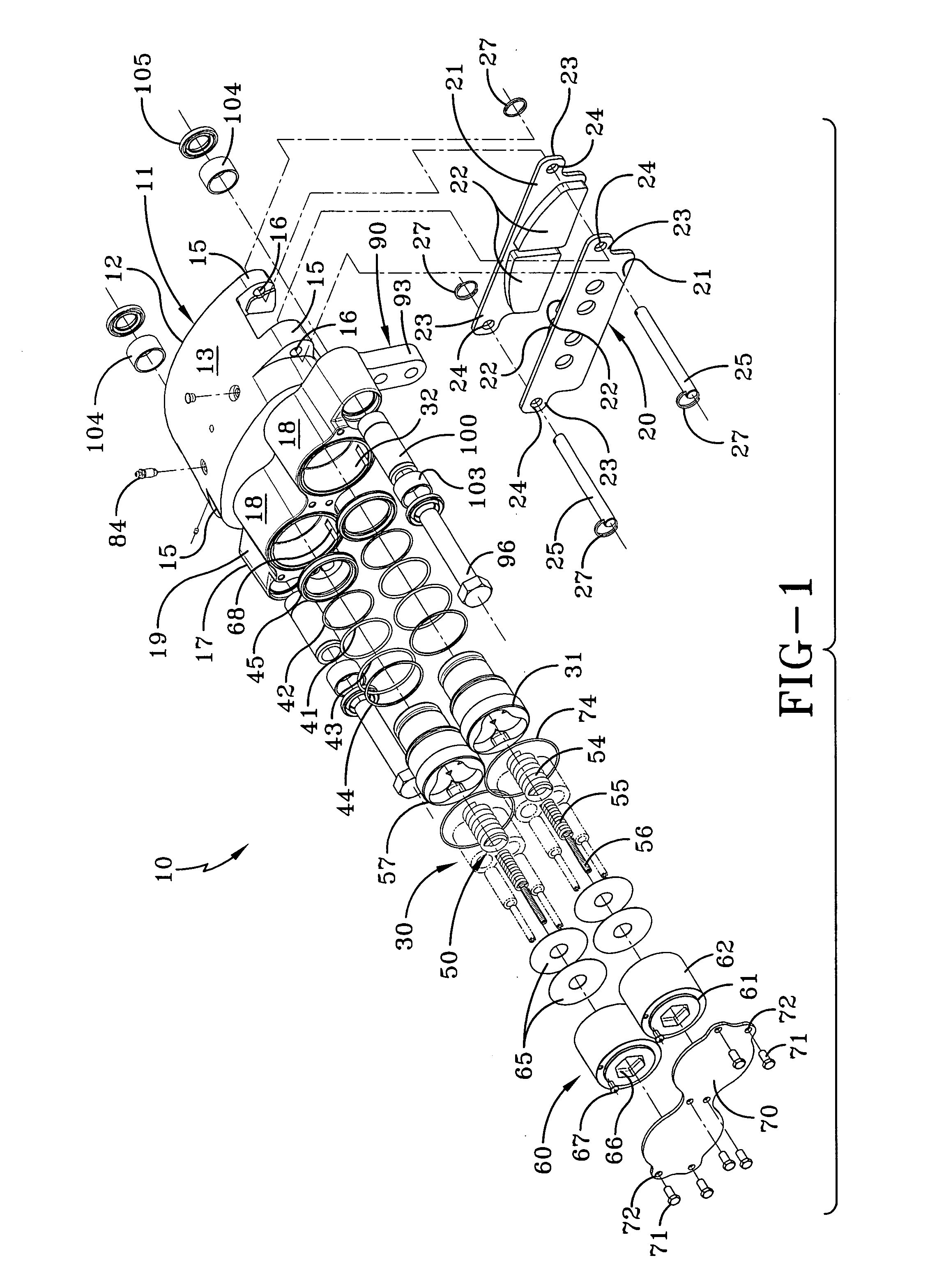
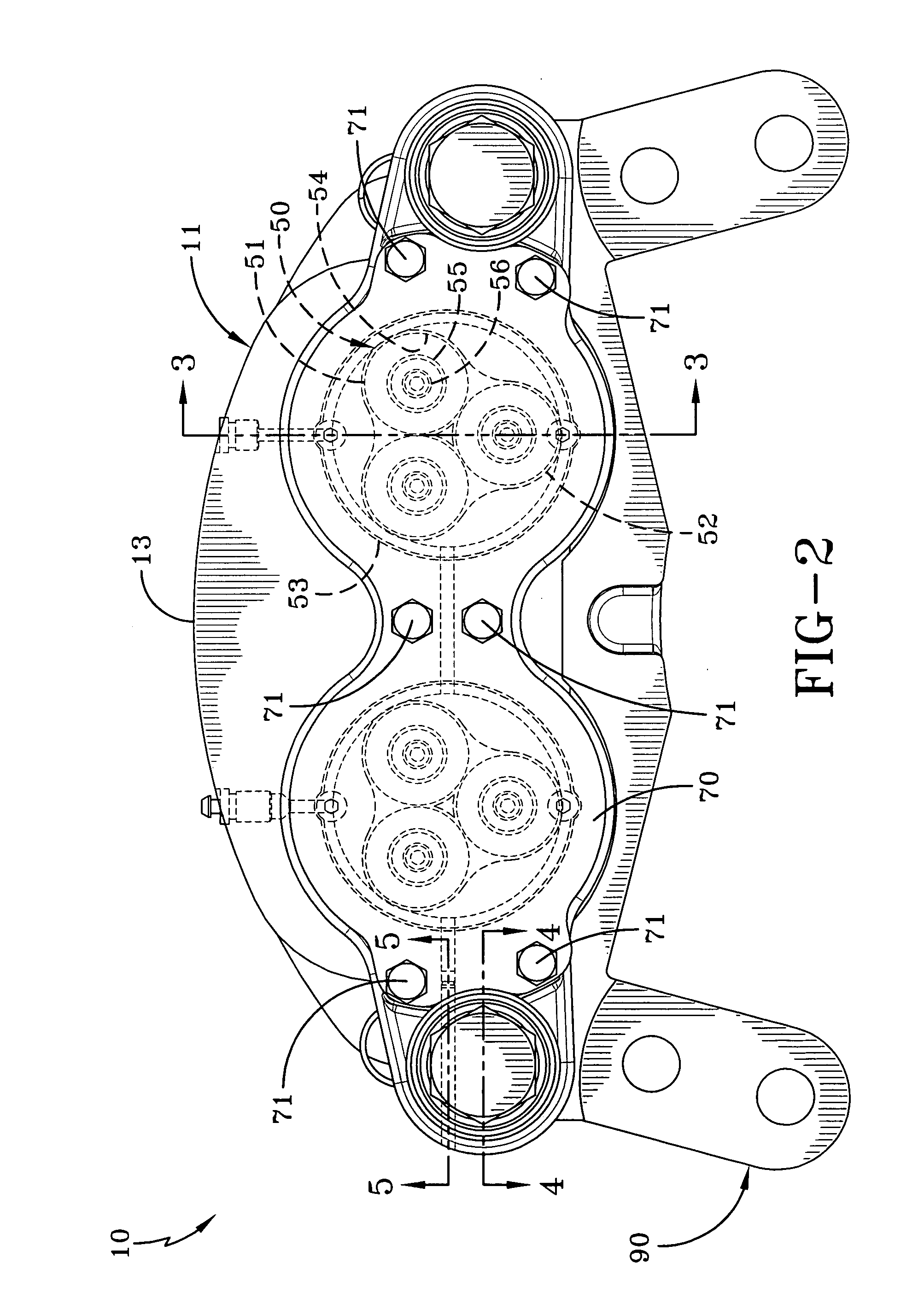
[0022]A caliper brake system according to the concepts of the present invention is generally indicated by the numeral 10 in FIGS. 1 and 2 of the drawings. The caliper brake system 10 includes a housing, generally indicated by the numeral 11, that carries and protects components thereof and locates it in operative relation to a conventional wheel rotor R, indicated in chain lines in FIGS. 3 and 8 of the drawings.

[0023]The housing 11 has a stator assembly end 12 having an upward curved surface 13 as seen in FIGS. 1-3. The stator assembly end 12 has a cavity 14 underlying curved surface 13 that is adapted to enclose a portion of the rotor R.

[0024]Referring particularly to FIGS. 1, 3 and 8, the cavity 14 in housing 11 also receives a portion of a stator assembly, generally indicated by the numeral 20. In particular, a pair of stator plates 21 are positioned within cavity 14 displaced axially to either side of rotor R so that a portion of rotor R is interposed therebetween. The stator pl...


PUM


Abstract

A caliper brake system includes a housing, a bore within the housing, and a piston slidably positioned within the bore. The brake system also includes a spring assembly, a fluid chamber defined by the bore and the piston, and a hydraulic fluid supply network. The spring assembly provides a biasing force to maintain the piston in an actuated position engaging a stator which engages the rotor of a vehicle. The hydraulic fluid supply network provides pressurized fluid to the fluid chamber to selectively overcome the biasing force of the spring assembly and move the piston to an unactuated position to release the rotor. Thus, the caliper brake is spring actuated and hydraulically released.

Description

[0001]This application claims priority of provisional U.S. Application No. 60 / 961,881 filed Jul. 25, 2007, which is incorporated herein by reference.TECHNICAL FIELD[0002]The present invention relates generally to caliper brake systems. More particularly, the present invention relates to a caliper brake system that may be employed in conjunction with parking brakes for trucks and off-road vehicles of various types. More specifically, the present invention relates to an automatic caliper brake system for vehicle parking brakes wherein the brake calipers are spring applied when the vehicle hydraulic system is turned off and hydraulically released when the vehicle hydraulic system is energized.BACKGROUND ART[0003]Caliper brakes are well known in the field of parking brakes, and are commonly used on off-road vehicles such as construction equipment to supply a braking force when the vehicle is stationary. These parking brakes must provide a relatively high braking force in order to preven...

Claims


Application Information

Patent Timeline
Patent Type & Authority Applications(United States)
IPC IPC(8): F16D55/224F16D65/18
CPCF16D59/02F16D65/18F16D2123/00F16D2121/14F16D2121/12
Inventor BALDEOSINGH, HOWARD H.DENNIS, BRIAN P.CRAWFORD, NORMAN D.POZIVILKO, PETER J.
Owner LAMBERT BRAKE
Why Eureka
Try Eureka