Method and apparatus to provide synchronous rectifying circuit for flyback power converters

a technology of synchronous rectifying and power converter, which is applied in the direction of electric variable regulation, process and machine control, instruments, etc., can solve the problem of limited maximum on time of power switch, and achieve the effect of improving the efficiency of power converter

Active Publication Date: 2009-01-29
SEMICON COMPONENTS IND LLC
View PDF11 Cites 33 Cited by
  • Summary
  • Abstract
  • Description
  • Claims
  • Application Information

AI Technical Summary

Benefits of technology

[0005]A synchronous rectifying circuit is developed to improve the efficiency of the power converter. The synchronous rectifying circuit includes a pulse generator for generating a pulse signal in response to the rising edge and the falling edge of a switching signal. The switching signal is utilized to switch a transformer and regulate the power converter. An isolation device, such as a pulse transformer or capacitors, is coupled to the pulse generator to transfer the pulse signal from the primary side of the transformer to the secondary side of the transformer. A synchronous rectifier comprises a power switch and a control circuit.

Problems solved by technology

Additionally, the maximum on time of the power

Method used


Image

  • Method and apparatus to provide synchronous rectifying circuit for flyback power converters
  • Method and apparatus to provide synchronous rectifying circuit for flyback power converters
  • Method and apparatus to provide synchronous rectifying circuit for flyback power converters

Examples


Embodiment Construction

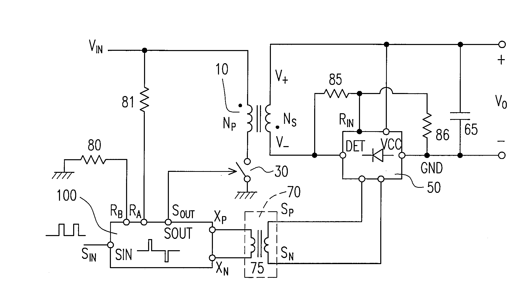
[0019]FIG. 1 shows an embodiment of a power converter with synchronous rectifier according to the present invention. The power converter includes a transformer 10 having a primary side and a secondary side. The primary side of the transformer 10 comprises a power switch 30 for switching the transformer 10. The secondary side includes a first terminal V+ and a second terminal V−. A switching voltage is produced across the second terminal V− and the first terminal V+ in response to the switching of the transformer 10. A synchronous rectifier 50 comprises a rectifying terminal DET connected to the second terminal V−. A ground terminal GND of the synchronous rectifier 50 is connected to the output of the power converter. An input terminal RIN is coupled to receive the switching voltage through resistors 85 and 86. A first input terminal SP and a second input terminal SN of the synchronous rectifier 50 are connected to the secondary side of an isolation device 70 to receive a pulse signa...


PUM


Abstract

A synchronous rectifying circuit is provided for flyback power converter. A pulse generator is utilized to generate a pulse signal in response to a leading edge and a trailing edge of a switching signal. The switching signal is used for switching the transformer of the power converter. An isolation device such as pulse transformer or small capacitors is coupled to the pulse generator for transferring the pulse signal through an isolation barrier of a transformer. A synchronous rectifier includes a power switch and a control circuit. The power switch is connected in between the secondary side of the transformer and the output of the power converter for the rectifying operation. The control circuit having a latch is operated to receive the pulse signal for controlling the power switch.

Description

BACKGROUND OF THE INVENTION[0001]1. Filed of Invention[0002]The present invention relates in general to a control circuit of power converter, and more particularly, to a synchronous rectifying control circuit for power converter.[0003]2. Description of Related Art[0004]An offline power converter includes a power transformer to provide isolation from AC line input to the output of the power converter for safety. In recent development, applying the synchronous rectifier on the secondary side of the transformer is to achieve a high efficiency conversion for power converters, such as “PWM controller for synchronous rectifier of flyback power converter” by Yang, et al. U.S. Pat. No. 6,995,991. However, the disadvantage of this prior art is the propagation delay of the switching signal detection and the phase-locking, which degrades the performance of the synchronous rectifier. Besides, the switching current detection causes additional power consumption by the ESR of the output capacitor....

Claims


Application Information

Patent Timeline
IPC IPC(8): H02M3/335
CPCY02B70/1475H02M3/33592Y02B70/10
Inventor YANG, TA-YUNGCHEN, TSO-MIN
Owner SEMICON COMPONENTS IND LLC
Why Eureka
Try Eureka