Antenna feed network for full duplex communication

a feed network and duplex communication technology, applied in the field of wireless transceivers, can solve the problems of reducing the local receiver's performance affecting the performance of the receiver, etc., and achieve the effects of inadequate filtering, high isolation, and transmission channels

Inactive Publication Date: 2009-01-29
KNOX MICHAEL E
View PDF39 Cites 65 Cited by
  • Summary
  • Abstract
  • Description
  • Claims
  • Application Information

AI Technical Summary

Benefits of technology

[0017]It is an object of the present invention to provide a duplex wireless communication device wherein the transmit channel to the receive channel insulation is improved over prior art arrangements. In particular, the present invention relates to an antenna feed network and a full duplex transceiver system including the antenna feed network. The antenna feed network provides high isolation between a transmit channel and a receive channel in the direction from the transmit channel to the receive channel in the full duplex transceiver. The antenna feed network allows the transceiver to operate using the same transmit and receive frequencies. The antenna feed network also allows the transceiver to operate using different transmit and receive frequencies. In an advantageous application the two different frequencies are close in frequency and are therefore inadequately filtered using a duplexing filter.

Problems solved by technology

It is known that operation of the local receiver during the time that the local transmitter is transmitting creates receiver problems as the transmitter energy leaks, couples and / or reflects into the receiver resulting in corruption, distortion, saturation and / or desensitization within the receiver.
If the system is designed to operate with the local transmitter and receiver using the same RF carrier frequency or with different transmit and receive frequencies that are close in RF carrier frequency such that the duplexing filter cannot adequately provide the required isolation, then a portion of the local transmitter's transmission signal energy will enter the local receiver and reduce the local receiver's performance.
For example, if a receiver front-end is driven into saturation from a high level RF signal that leaked, coupled or reflected from the transmitter of the transceiver, the receiver performance could be significantly degraded.
This undesired leakage typically occurs due to practical limitations in design of the circulator 3.
Additionally, a portion of the transmission signal is reflected from the antenna 4 due to mismatch between a transmission line impedance and the antenna's input impedance and results in second undesired path, or reflected signal 14.
It is known that these undesired signals 13 and 14 will create problems if the energy level is high enough to cause corruption, distortion, saturation and / or desensitization within the receiver.
This signal level will severely drive the receiver front-end into compression thus greatly reducing receiver performance.
For the case of an antenna with a 20 dB return loss, the reflection 14 results in a signal level into the front-end of +10 dBm (10 milliwatts), which also compresses the receiver and greatly reduces receiver performance.
This isolation level is very difficult to achieve in a low-cost circulator.
In addition, the return loss of the antenna would need to be greater that 30 dB (1.06:1 VSWR) which is also difficult to achieve over the full operating system bandwidth.
A two-antenna configuration is less desirable than a single antenna system due to the increased physical size and higher antenna cost.
In addition, a two-antenna system may result in reduced performance in a multipath environment.
In a full duplex transceiver operating using a single antenna, the leakage through the circulator and reflection from the antenna represent a technical problem to the performance of the receiver.

Method used


Image

  • Antenna feed network for full duplex communication
  • Antenna feed network for full duplex communication
  • Antenna feed network for full duplex communication

Examples


Embodiment Construction

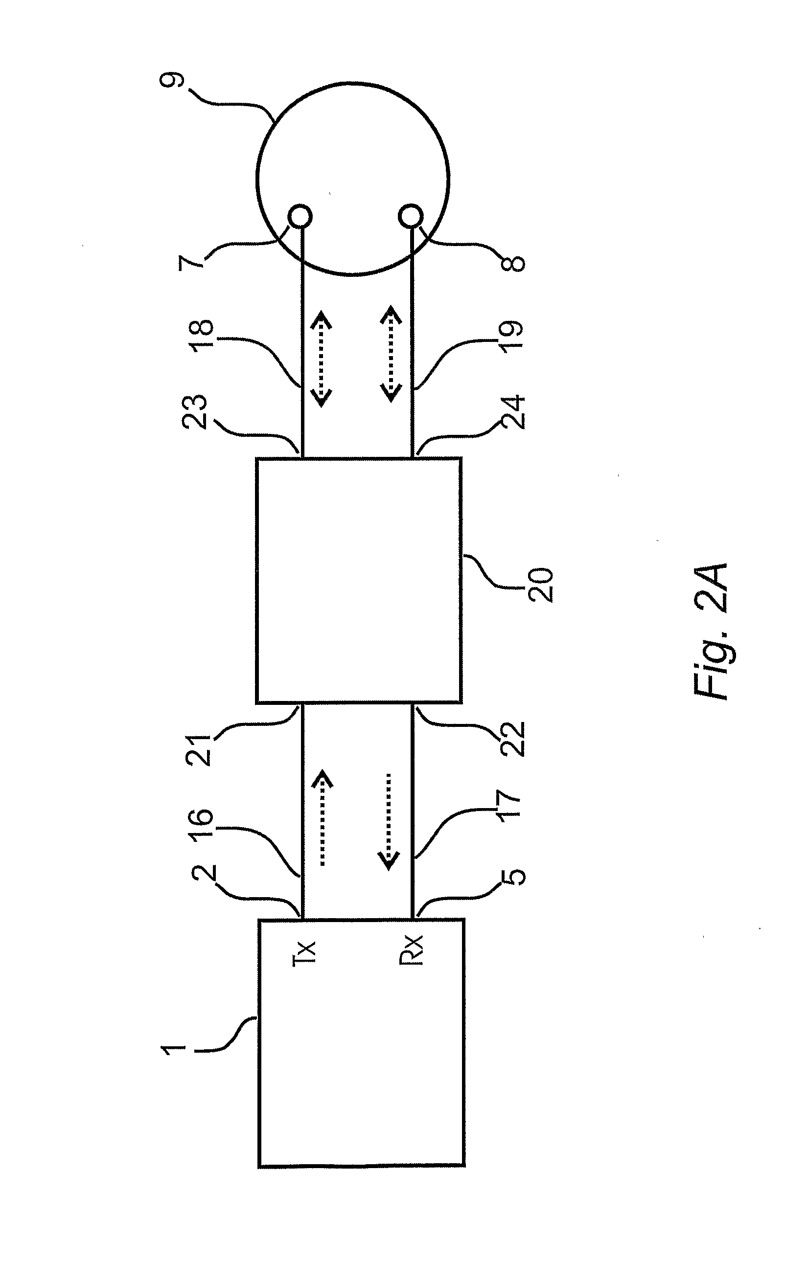
[0057]Referring to FIG. 2A, an antenna feed network 20 is connected between a full duplex transceiver 1 and a CP antenna 9. The full duplex transceiver 1 has a transmitter output 2 and a receiver input 5. The antenna feed network 20 has a transmit channel input 21, a receive channel output 22 and first and second bi-directional network antenna ports 23 and 24 for connection to the CP antenna 9. The CP antenna 9 contains a first antenna feed point 7 and a second antenna feed port 8.

[0058]The example of the present invention shown in FIG. 2A is a preferred embodiment utilizing a CP antenna having two feeds as an antenna assembly; it is however understood that for the purpose of this disclosure an antenna assembly is considered to include two antennas, either disposed independent of one another or in a combined structure, may be substituted for the CP antenna 9, to present two feeds provided that the two antennas function together to have input characteristics wherein input and output ...


PUM


Abstract

The present invention provides a wireless device for effecting two way wireless transmission, an antenna feed network (20), and a patch antenna. The wireless device includes an antenna assembly having first and second feed inputs (7 and 8) and accepting first and second antenna feed signals shifted a feed signal phase difference apart. The antenna assembly (9) receives radiated signals and produces a first received signal and second received signal at the first and second feed inputs (7 and 8). First and second reflected feed signals are also produced at the first and second feed inputs (7 and 8). A transmitter produces a transmission signal and a receiver receives a received signal composed of at least a portion of the at least one of the first and second received signals from the antenna assembly (9) while the transmission signal is being transmitted by the antenna assembly (9). The antenna feed network (20) interconnects the transmitter port (2), the receiver port (5), and the antenna assembly (9) to apply the transmission signal to the first and second feed inputs (7 and 8) and to simultaneously receive at least one of the first and second received signals from the first and second feed inputs (7 and 8) and produce the received signal therefrom while effecting cancellation of the first and second reflected feed signals.

Description

TECHNICAL FIELD[0001]The present invention relates to wireless transceivers that operate in full duplex mode providing the simultaneous transmission and reception of radio signals. In particular, but not exclusively, the present invention relates to wireless transceivers that are provided with a means to isolate signals transmitted by the transmitter of the wireless transceiver and received by a receiver of the wireless transceiver.BACKGROUND OF THE INVENTION[0002]Modern wireless communication, radar and radio frequency identification (RFID) systems often operate under full duplex operation. A wireless transceiver comprises of a local transmitter and a local receiver. Full duplex operation occurs when a local transmitter is actively transmitting RF signals during the same time that a local receiver is detecting RF signals and / or backscatter from the surrounding environment. The local transmitter and local receiver are typically in close proximity to one another and are often placed ...

Claims


Application Information

Patent Timeline
Patent Type & Authority Applications(United States)
IPC IPC(8): H04J13/02
CPCH01Q9/0435
Inventor KNOX, MICHAEL E.
Owner KNOX MICHAEL E
Why Eureka
Try Eureka